
Is your Bang and Olufsen BeoCenter 9000 refusing to play CDs? Does the door reopen after loading or take too long finding the tracks? If so there may be a simple way to fix it.
Christmas lunchtime and the trusty BeoCenter 9000’s CD refused to play Dianna Krall’s Christmas Songs so I’m in the doghouse again. The 9000’s CD player had been temperamental for a while and a simple Bluetooth interface had been an easier option but never sounded as good as the CD. The fault appeared intermittent with certain CDs just popping the lid open or taking ages to recognise the tracks. Cleaning the CD player’s lens with alcohol and a cotton bud did not improve the fault.
A quick Google search suggested an electrolytic capacitor the most likely culprit on the Beoworld forum – BeoCenter 9000 CD Problem. “Replace the C2103 capacitor on the servo board” — an easy fix they say… Well yes and no, it took me a couple of hours but it was worth it in the end.
Warning: Unplug the power lead and don’t attempt to operate your BeoCenter with the top cover open!
The 9000 is a bit of a beast and needs a large area to service it. The secret to opening the BeoCenter is a Youtube video away, see – Bang & Olufsen Beocenter 9000 Repair. But take care! My BeoCenter’s glass panels had become loose and could come crashing out if you blindly follow the helpful video. I remembered my 9000’s lower glass panel arrived detached and had just rested in place ever since so I removed it and the edging before attempting to open the top. The higher panel was also loose and also lifted free. If your panels are still partly glued in place there are two screws underneath on the left had side that when removed allow the top and bottom panels to slide to the right and lift off to be on the safe side.
-
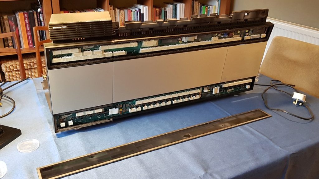
- BeoCenter 9000 Top Control Panel with Glass Removed

-
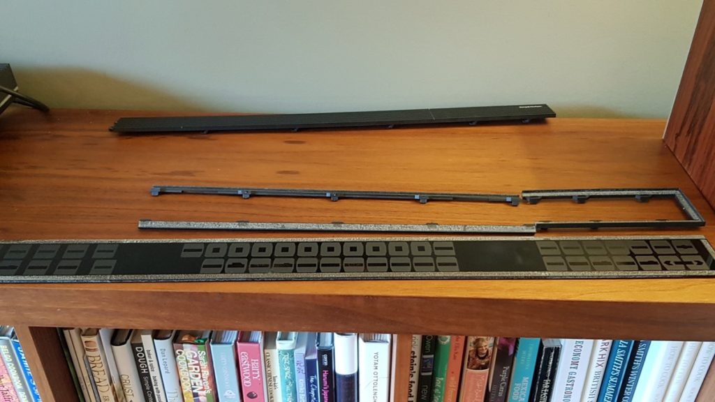
- Lower Glass Panel Removed

-
- BeoCenter 9000 CD service mode

-
- BeoCenter 9000 stay and CD transport

-
- CD Transport connectors

-
- CD servo Faulty Capacitor

-
- CD servo Capacitor Replaced

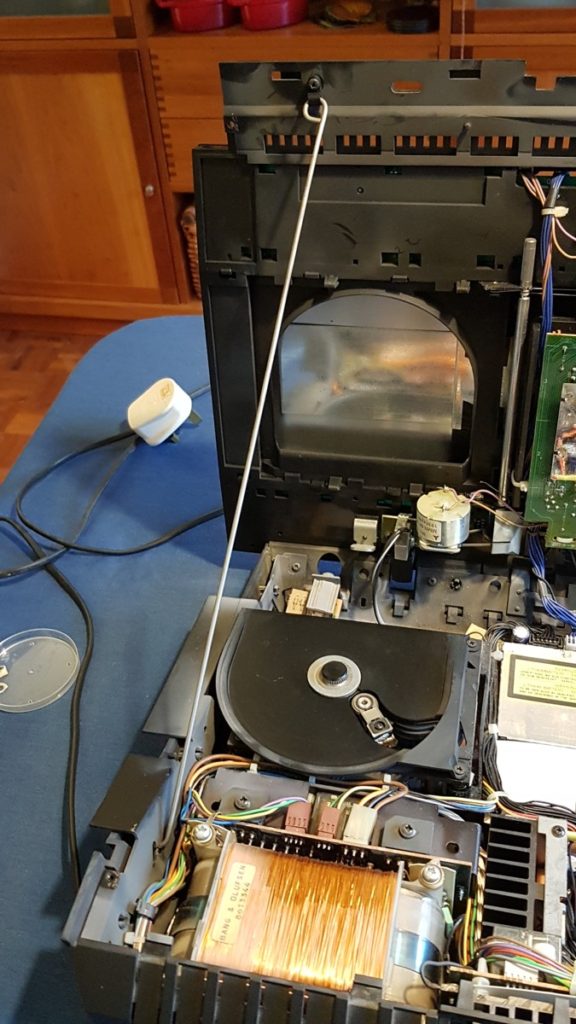
The B&O designers used the car bonnet approach for servicing repairs allowing the top to hinge up from the back using a metal stay to prop it open. You will need Torx or star screwdriver bits to remove the fixings and lift the top. Unfortunately the white plastic clip holding the stay to the top had become brittle and disintegrated so had to be replaced with a 3/16 P-clip. See photo showing the clip and stay which locks in place on the right had side of the base next to the transformer. It’s worth checking the stay is secure as the top is very heavy and could come crashing down just when you are about to remove the delicate CD transport!
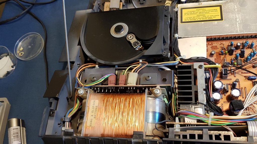
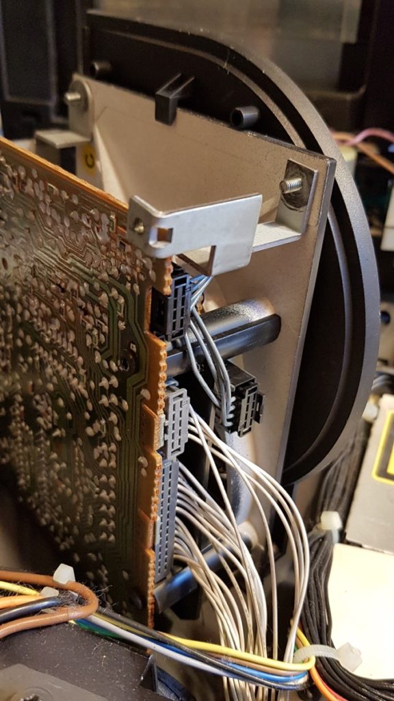
Removing the CD transport to access the lower circuit board needs a steady hand and patience. Need to undo the two lower screws on the right hand side of the CD (when looking from the back). Using a magnetic screwdriver tip helps avoid the fixings disappearing into the beast. The black plastic bracket retaining the CD mount can then be removed – take care not to loose the springs and small mounts that the transport sits in.
Once clear the CD transport can be lifted away from the base to access the two grey edge connectors. See photo. Use a small screwdriver to gently lever the centre clip that hold each connector in place. You don’t need to break any circuit board to do this. Best avoid pulling the grey wires again use a small screw driver to lever the connector free each end once the centre clip is free.
Locating the Capacitor
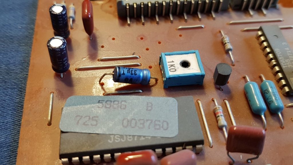
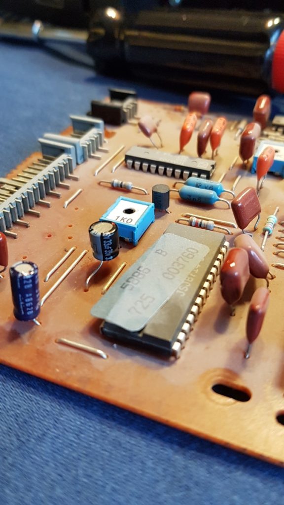
The blue Mullard / Philips 33µF capacitor is located on the lower PCB which is attached with 4 screws, a black edge connector and a thin flexible PCB ribbon cable. The ribbon is held in place by a white clip that can be pulled up to unlock. I replaced the axial capacitor with a 30v radial type with two 90 degree bends so the leads do not pull apart from the capacitor body.
You may read posts that say to replace all the electrolytic capacitors and buy a whole kit of capacitors. I prefer to do minimal damage and suggest checking them first with an ohms test using a simple multimeter if you don’t have a capacitance meter. On the multimeter higher resistance setting, say 20kΩ (ohms) range, check the time it takes to change resistance then reverse the leads and compare the time the other way round. For example in circuit the 47µF caps took around 4 seconds to go from a few ohms to >20k either way round – the same as a new 47µF capacitor out of circuit so no need to waste time changing them. If it changed resistance in less than a second like the blue 33µF I’d be suspicious and change it.
Reassembly is quite simple just remember to insert the ribbon cable fully into the white connector and push the locking piece back down to hold it in place. Sitting the CD transport back into the 4 springs is a bit fiddly as it slides back down into position and locks in place using the black plastic bracket.
With the top back down you can plug in and with any luck the CD will be fixed. My BeoCenter had one more trick to play – I had by mistake plugged the left and right speaker DIN plugs into the 2nd channel output sockets. It’s easy to do if your BeoCenter is up against a wall the speaker plugs are hidden unlike the input sockets which are accessed from a flap above. So while the CD played the sound was quiet and distorted. I thought I’d damaged the connectors until I tried the radio and vinyl LP sources only to find these sounded awful as well. So I swapped over the speaker plugs and the volume and quality was restored! When I get time I’ll take it apart and clean the DIN sockets. The silver contacts go black with tarnish over time especially when not in use. Note to self — the circuit shows relay contacts are also used to disconnect the speakers when headphones are plugged in so these may well need cleaning as well. Good luck!
PS 8-Jan-2024
Updated links to Beoworld forum which had since been archived.
Several readers have found the fault may return after replacing C2103, the 33µF capacitor. So here are some additional things to check.
The BeoCenter 9000 uses a Philips CDM2 mechanism and the service manual is available from Elekro Tanya – PHILIPS CDM2 CD MECHANISM Service Manual download, schematics, eeprom …
Here’s an extract from page 19 showing the laser drive circuit with the suspect C2103 electrolytic capacitor.
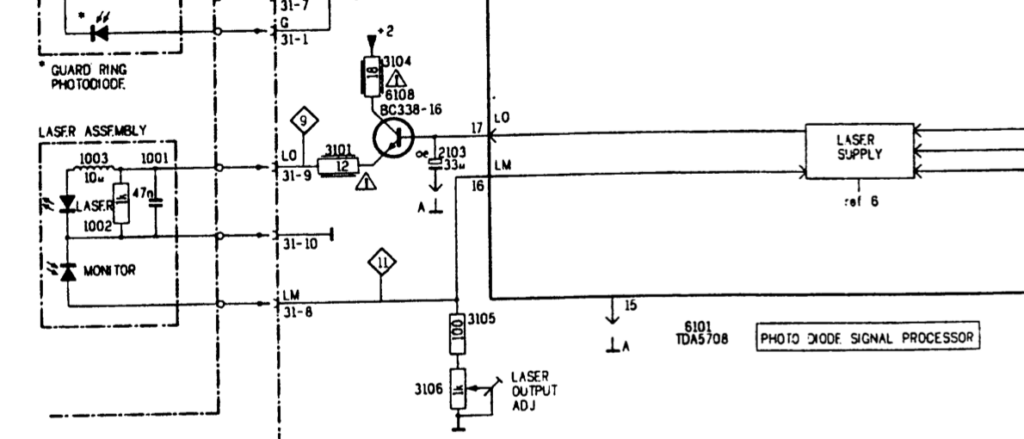
Philips CDM2 Laser driver with C2103
The capacitor acts as a reservoir to provide enough voltage for BC338 to power the laser LED. Notice the two current limiting resistors 3104 (18Ω – brown grey black) and 3101 (12Ω – brown red black) have warning triangles. This may indicate they are rated to blow if there’s a laser fault short circuit. So check both values using a multimeter are within 5%. Change if out of spec or if there’s any brown discolouration to the banding.
The 1KΩ preset 3106 controls the laser output. Presets can age and become intermittent due to contact tarnishing. Looking back at the photos above, the preset is the square blue sided component adjacent to the capacitor. The circuit shows the wiper reduces the resistance so if it’s tarnished and high resistance the laser drive will be too low causing malfunction much like the faulty capacitor. Check the resistance between R3105 and ground – it should measure less than 1KΩ.
Use a fine pencil to mark the wiper’s position and apply a very small amount of switch cleaner. Using a hex tool rotate the preset back and forth very slightly to ensure the wiper contact is clean – take care to return it to the pencil mark starting position so you don’t change its factory setting.
Finally check the foil connections to the laser assembly and diode assembly are clean, not tarnished and fully engaged when you reassemble. Any increased contact resistance will likely cause the CD reading errors and mistracking.
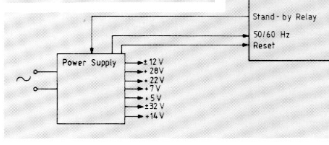
BeoCenter 9000 power rails
CDM4 Power supply
Philips CDM4 power supplies
See Elekro Tanya for CDM4 full schematics PHILIPS CDM4 D-8870-8873-8874 STEREO RADIO-RECORDER TR … – Elektrotanya
14/01/2019 at 5:09 pm
Did you try cleaning the CD first?
07/02/2019 at 9:09 pm
Hi Dave, yes and that’s what I’d thought was the problem for a long time. The faulty capacitor causes a fault similar to a dusty CD or lens. Often a CD would refuse to play so we would take it out give it a quick clean pop it back and it would start to play. But another CD would just spin then open the lid and no amount of cleaning or dusting the lens would get it to play. In the end the 9000 refused to play the usual favourites after cleaning so it had to be the player.
22/06/2019 at 10:15 am
Hello,
Thank you for the good article. Can I ask a question?
I have a PDF service manual for Beocenter9000. But it is written in German and French and then difficult to understand. How can I get an English service manual?
22/06/2019 at 7:13 pm
Hi – yes, here’s a useful site that has many service manuals – try https://elektrotanya.com/bang-olufsen_beocenter-9000_2501_2502_2503_2504_2505_2049.pdf/download.html
04/11/2019 at 6:58 pm
Hi Team, I’ve replaced the capacitor on question and it worked great for few weeks, then the fault occurred again.
I’ve changed the same capacitor again, and once again it worked great but for one day only!
What can be causing this? Do I need to change other capacitors? If so which ones please. I would really appreciate the comprehensive answer and help.
Thank you so much!
18/03/2023 at 6:21 pm
Hi Adam,
I have the same issue, I replaced the caps and the first CD played, then not again.
Did you fix yours? If so how?
Regards
Terry
14/01/2022 at 1:00 pm
Bonjour, Quelqu’un pourrait-il me donner l’identification des fils aboutissant sur le connecteur DIN 24 broches de la platine CD sur une chaîne Beocenter 9000 type 2501 ?
Dans l’espoir d’une réponse, je vous remercie par avance.
15/01/2022 at 3:20 pm
Bonjour, vous pouvez essayer le manuel d’entretien qui est en français – https://elektrotanya.com/bang-olufsen_beocenter-9000_2501_2502_2503_2504_2505_2049.pdf/download.html
Vous pouvez également essayer de rechercher le mécanisme Philips CD qui peut avoir des détails sur la connexion DIN utilisée. Bonne chance!
11/11/2022 at 1:53 pm
Hi, any suggestion how to restore door cables into position? Thank you
11/11/2022 at 8:47 pm
Mat, there are details of the mechanism (section 7-5, 7-6) in the service manual. You can download the service manual free if you register from the excellent site hifiengine see Beocenter 9000 The manual in in French and German. I need to fix the CD slide door on my 9000 so have not tried yet so let us know how you get on.
12/11/2022 at 8:53 pm
https://beomanuals.com/pdf-download_v2.php
English version found… 🙂 pages 90-91
14/11/2022 at 10:53 am
Thanks! The link didn’t work but the set of manuals are available here https://beomanuals.com/manuals/Beocenter/Beocenter%209000/
14/11/2022 at 11:09 am
Update from Mat – this shows how the cables route through (English subtitles)
“the most valuable commnet, as it is really hard to find, min 22,30…”
https://www.youtube.com/watch?v=FCUBMlWrCow&t=1081s
03/02/2023 at 10:48 pm
I followed your instructions and replaced the capacitor and now my CD player works. The amazing part is I’ve never done anything like this before but I took a chance and it worked. Just wish you would have included a few more detailed photos but thank you. You saved my Beocenter 9000.
04/02/2023 at 11:08 am
Happy to hear you fixed your Beocenter and the CD works again. Well done for having a go – it’s good to know another piece of retro tech has been saved. We use our Beocenter most days and the CD player still runs well. It can be rather temperamental on some CDs and may fail on Load CD but then play when CD is selected so will investigate when time permits. Remembering to take enough photos is a challenge and know a video would often be better. Thanks for taking time to let us know.
07/05/2023 at 11:46 pm
Brilliant and well documented. I used your instructions to get the cd player in my 9000 working. :-). Excellent and thanks!!
08/05/2023 at 7:15 am
Good to hear, many thanks for your kind comments.
08/01/2024 at 7:12 pm
Good evening all, I’ve been following all post and have done the resister change only to find the the problem still occurs on my beocentre 9000 version 1, the disk player will play for about 90 seconds then starts to break up then cuts out but if I go from cd straight to the tape deck then back to the cd player it’s starts to play fine again but only for the same time then cuts out again has anyone ever had this problem thanks ,Matt
08/01/2024 at 7:37 pm
Hello Matthew, my post focuses on replacing C2103 as suggested on the archived BeoWorld forum. I’ve just updated the link in my post as it had changed so apologies if this may have confused you. The new BeoWorld forum does mention a resistor for another CD fault but your problem seems more likely to need the 33µF capacitor change.
08/01/2024 at 8:21 pm
Thanks for the fast response Rick please can you tell me were this Capacitor is located please.
08/01/2024 at 10:06 pm
Sure, the blue cap is found on the lower circuit board below the CD mechanism. See photos in this blog post showing its position on the servo PCB next to the 1K preset potentiometer.
08/01/2024 at 10:09 pm
Hi Rick that’s the cap iv all ready changed so hod only knows why it’s still having the same problem
08/01/2024 at 11:02 pm
I’ve added some more things to try at the end of the post. Let us know how you get on.
09/01/2024 at 6:38 pm
Hi Rick I’ve checked all resistors and they are bang on only thing that is different is the 1k preset shown in your pictures is different to mine, as mine is 4 k7 preset!
09/01/2024 at 7:01 pm
Okay, so you must have the CDM4 mechanism see https://elektrotanya.com/philips_cdm4_d-8870-8873-8874_stereo_radio-recorder_tr-8837_tr8847_cd-supplement_sm.pdf/download.html This has a 220R + 4k7R laser adjustment but still uses the 33µF cap. There are some voltages marked in the service manual so you could check they are similar.
10/01/2024 at 10:41 am
Hi Rick I cleaned the pitch control with some contact spray and checked the ribbon cables I reinstalled the the player and everything worked fine and the player played to songs only to get to the 3rd song and the fault came back it’s really weird it plays but the sound is breaking up, maybe I’m looking in the wrong place
10/01/2024 at 11:26 am
Guess you checked the lens optics are clean, it could have picked up dust during reassembly? IPA and cotton bud. Failing that does the lens arm move freely and smoothly – check if it’s catching anywhere through the arc due to dust / fluff. These Philips CD mechanisms were some of the best ever made so it can be fixed.
10/01/2024 at 12:32 pm
Yeah I’ve done all the above Rick it’s so strange that it reads the disc perfectly, it tells you how many songs are on the cd and plays straight away, it seems the longer I have the unit switched on the worse it gets, is the cd and tape deck run from the same power supply or are they on different voltage rails!
10/01/2024 at 2:26 pm
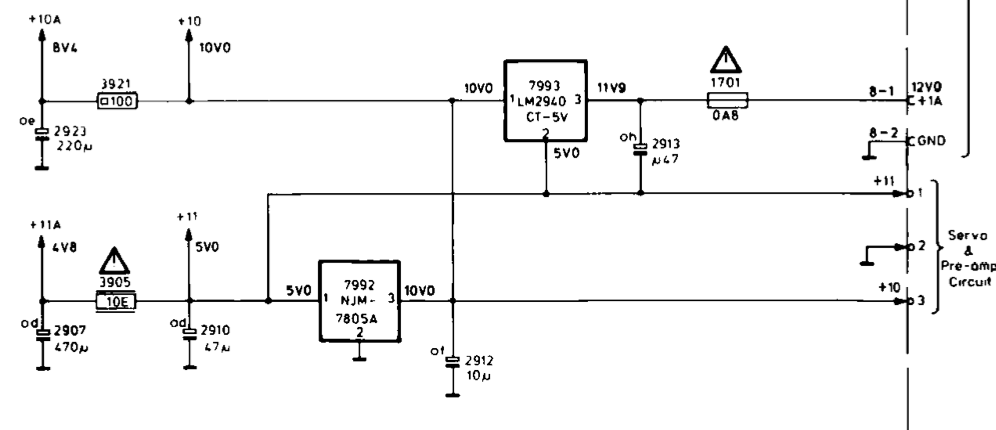
May need to tweak the 4k7 pot to adjust laser level in case it’s moved? Worth checking power supplies are not drifting. I’ve added some schematics showing the 9000’s supply rails and the CDM4 supply. Not sure how your Beocenter is wired as it uses a different mechanism to mine but suspect it’s powered from the 12v supply. Given the CDM4 uses two stacked 5v regulators to provide the 5v and 10v internally I’d check both these first. Then recap the other electrolytics in the CDM4 to be sure.
12/06/2024 at 2:11 pm
Have changed the capacitor, but the cd Will only play 9 tracks. Any good ideas.
BR Mogens A
13/06/2024 at 9:21 pm
So does this happen on a different cd with more than 9 tracks? My Beocenter has refused to play some cds and not others and after cleaning the lens of dust plays okay. If the optics are clean the laser lens arm movement may be restricted so check it swings across the full arc without resistance and clean if necessary. Failing that the laser level may have reduced over the years and need increasing. Check the Philips service manual for adjustment with care.
14/06/2024 at 7:40 am
Thanks Rick , the arm movement was the problem.
Your answer cured the problem.
14/06/2024 at 8:09 am
Excellent, thanks for your feedback.
23/07/2024 at 7:57 am
Condoraudio.com recommands to replace the capacitor by a 47uF 25 v
Here is the link: http://www.condoraudio.com/wp-content/uploads/Projects/Philips-CD650-CD-Player-Restoration-Repair.pdf
Best regards
23/07/2024 at 11:09 am
Thanks for the recommendation and link. There are many suggestions to consider in the condor audio post not all I agree with. For example, I’m not in favour of simply replacing all electrolytic capacitors without finding the component at fault. Yes, there are known problem types that make sense to change, but damage to PCBs by needless replacement can introduce a greater risk of failure!
30/07/2024 at 1:42 pm
Rick,
If I want to work on a cd player, do I need to take ESD-safe measures?
30/07/2024 at 2:57 pm
Hi Bert, only really need to when changing ICs or MOSFET devices. I tend to touch an earthed device, like my angle poise lamp on my bench, just before I handle these devices to make sure I’m not charged. Can be a problem on hot dry days walking on carpets or removing pullovers!
30/07/2024 at 1:46 pm
Rick,
In my Beocenter 9000 is a Philips cdm4/24 pkayer.
Can I replace it by a Philips cdm4/19 player without adjustments ?
Best regards
30/07/2024 at 3:02 pm
Hi Bert, honestly not seen a cdm4/19 so can’t advise. If you have the Philips service manuals and the connections are the same it may work. There are some useful details about the range here – https://www.hifi-advice.com/blog/classics/digital-classics/marantz-philips-classics-2/philips-cdm-mechanisms-page-2-cdm-4-cdm-1-mkii-cdm-9/
24/09/2024 at 5:06 am
I have a Bang & Olufsen Beocenter 9300
Both the tape deck and CD player would not open
24/09/2024 at 9:34 am
Does any function work on your 9300? Can you hear the motors run?
The open/close motors are driven from the 14v supply – see p1-15 service manual. So check pin 2 on IC2/3 for 14v and if nothing trace back G69 and check the fuses in the power supply. There’s no 14v output shown on the supply board p1-9 so probably the 23v feeds a regulator downstream.
03/10/2024 at 3:10 pm
Hi I have a Bang and Olufsen beocenter 9000 and the cd stabilizing clip is missing this is the part that you put the cd on (the centre of the cd) I have tried everywhere does any one have a clue ?
Thanks