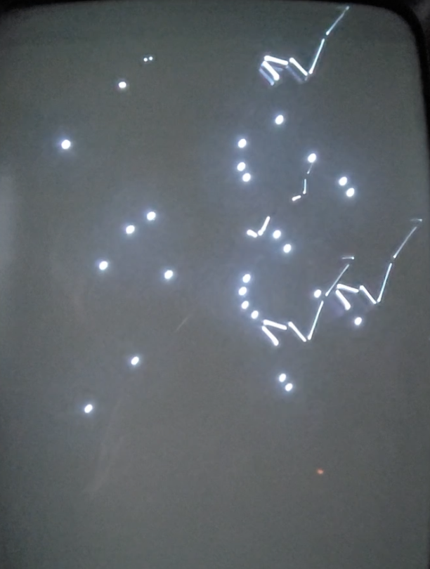
Hello, do you have a Vectrex video games console which displays odd dots or lines like this one? If so, I’ll run through some ideas that helped fix the Vectrex video faults I found.
Warning: The Vectrex has dangerously high voltages inside and must not be operated with the casing removed. The CRT display can also retain high voltages after switch off and must be discharged before service.
The Vectrex is not the usual subject of posts here at Retro Radio so I’ll begin with how the retro games console arrived in my workshop for repair. If you’re in a hurry you can skip the intro and dive into the list of suspect components to try below.
Volunteering at our local Repair Cafe takes me past a real cafe That Retro Place and when I popped in I got chatting to the owner. Inside I found all kinds of games consoles along with board games available to play with an excellent latte or cappuccino. On the counter was a strange looking console with a portrait style CRT monitor. The display was bright and sharp – no hint of jagged lines that are common on similar consoles from the 1980s.
The Vectrex, as its name suggests, is a vector display device – similar to the type used in analogue oscilloscopes. In fact there’s an open source project called Scopetrex that uses the Vectrex chipset to drive a scope, but that’s another story…
Lines are drawn from point to point to make a display using a series of X and Y coordinates. Other games consoles of this era used a standard TV style display with a raster that scans across the screen from top to bottom. This creates the familiar jagged zig zag lines as individual pixels are used to approximate straight lines.
Havard said he had another Vectrex that he’s been trying to repair for a friend and asked if I would like to have a go at fixing the faulty display. He’d tried but could not locate the problem. This was not the usual retro technology I normally get involved with but as I’d started my electronics career with Decca Radar, working with analogue vector display systems so I agreed to take on the challenge.
Vectrex examination
Powered up, I could hear faint beeps and a buzz, so the audio and logic board appeared to function. The CRT display was blank even with the rear brightness control turned fully up. I could see the CRT heater glowing so there was some hope I thought. Time to take a look inside.
As mentioned above, there are hazardous voltages inside the Vectrex and you need to ensure the CRT is discharged safely before attempting to investigate inside after unplugging from mains power. Google will suggest safe ways to do this if you are unsure.
Unfortunately the Vectrex’s case was broken as the console had suffered a fall sometime ago and languished somewhere to gather dust. I checked for damage to the power board that had housed some heavy components and found no evidence of cracks or broken joints. The logic board also appeared undamaged although it was caked in dust and grime from its abandonment.
I downloaded the service manual and troubleshooting guide (see useful links below) to identify how power was routed from mains transformer to the circuit boards. There are several DC supply rails +5v, +9v, -5v, -9v, and -13v. The +/- 5v also have ‘analogue’ versions that have additional filtering. The positive supplies all measured correctly but there was only 0.65 instead of -13v on the logic board. Tracing back I found no -5 or -9v supplies at all. Note the +9v supply actually measured over 11v DC as it’s unregulated, so don’t be too concerned it it’s not exactly 9v. The +/- 5v supplies, however, should be correct.
As the negative supply rectifiers and reservoir capacitors all measured okay, I traced back the fault to the power switch and began the Vectrex challenge to fix a series of faults that unfolded.
List of suspect and faulty components
Here’s a list of usual and not so usual suspect components and the faults caused based on my example. Note the digital to analogue (DAC) signal path for the X and Y vector generation and the Z (intensity /blanking) pass through a chain of components, each of which affect the final shape displayed. So a fault in any one component can affect the signal downstream and lead to confusion. It’s best to start investigation at the vector’s source the DAC.
- Power Switch – Fault: no video display
- DAC – MC1408P8 – Fault: characters all show as dots
- Integrator Op Amp – LF347 – Fault: distorted vectors
- DAC Op Amps – LF353 – Fault: distorted vectors
- Polystyrene Capacitors – 4700pf / 10000pF polystyrene Suflex – Fault Z-axis intensity
- 0v Reference – Fault: long tail vectors
Power Switch
Fault: no video but audio beeps.
A google search returns the power switch as a common Vectrex component to fail. Most suggest replacing the switch which is integrated with the volume control. It uses a double pole, switching both the secondary AC feeds from the mains transformer. Note this means the transformer’s primary is always powered with mains voltage when the Vectrex is plugged in. Always unplug or switch off your console when not in use to avoid unnecessary power drain and reduce your phantom load!
On this Vectrex only one of the poles had failed, the AC feed to the -9V supply. So although the +9v / +5v supplies functioned, allowing the logic and audio to sound, there was no display. Unfortunately, as I was to discover, the missing negative supply had taken out several chips on the analogue circuitry.
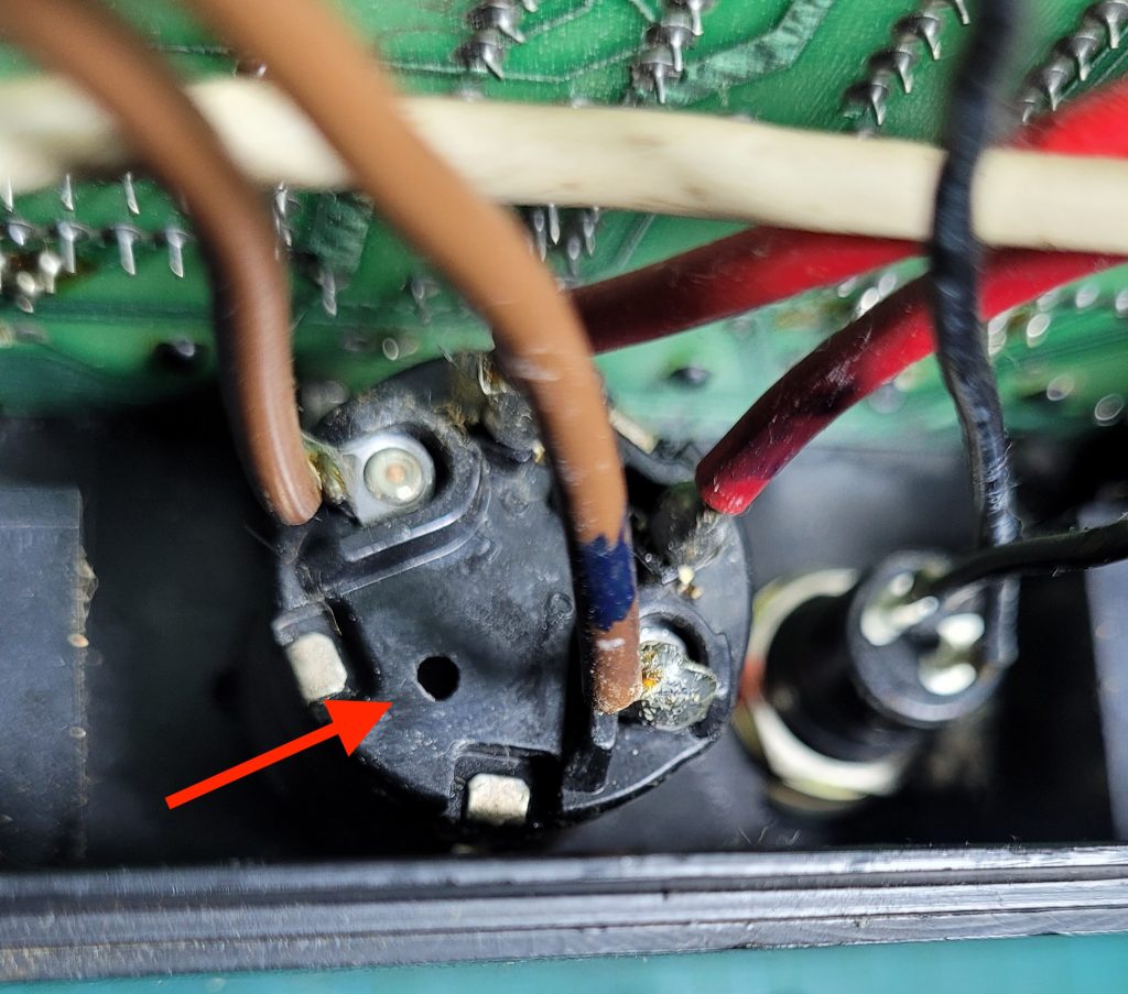
I decided to drill a small hole in the control’s plastic case and squirt some non lubricating switch cleaner inside to try and remove the contact oxide. After several switch operations the resistance had lowered and the Vectrex video sprang into life. Well some dots and lines appeared at least!
Contact cleaner without the hole is unlikely to work as the control moulding is fully encapsulated unlike some switched potentiometers that have an open slot. You may choose to replace the volume control. If you do, ensure you note each of the control’s wires and rewire correctly.
Smith Engineering could have improved the design by switching the mains transformer primary rather than secondary so that partial switch failure would stop both +/- supplies. This would avoid the asymmetrical power failure I discovered and subsequent component damage. Of course this would need suitable double insulation to ensure mains voltages are not exposed close to the logic board.
DAC – MC1408P8
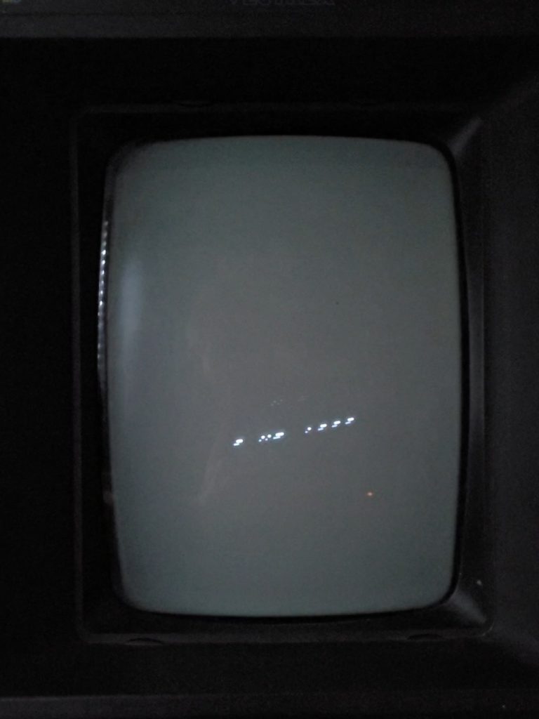
Fault: text characters all show as dots – see below.
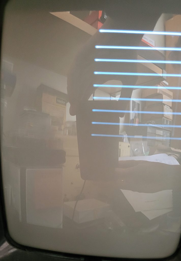
With the -9v power supply restored the Vectrex displayed a diagonal line of dots instead of the Mine Storm copyright and date at start up. After some investigation I found the voltage on +Vref pin 14 on the DAC seemed too low and suspected the chip was damaged so ordered a replacement.
Fortunately the MC1408P8 digital to analogue converter was socketed and it was simple to replace. This improved the text and the built in Mind Storm video to some vectors, but still not correctly. There were strange tails and misaligned segments.
The service manual (see links below) suggests adjusting R333 and R335 to set the integrator offset and align X and Y axis cross lines. This appeared to make no difference, but you really need the Vectrex Test Cartridge for this so one was ordered.
Integrator Op Amp – LF347
Fault: distorted vectors
The integrator op-amp uses a quad op-amp LF347 which was socketed and easy to change. A replacement showed a little improvement to the vector shape but the diagonal tails persisted and the text appeared as a staircase of dots. I began to suspect all the chips fed by the missing -5V analogue supply line may be damaged so I turned attention to the feeder op amp and 4052B demultiplexer chip.
DAC Op Amps – LF353
Fault: distorted vectors
As the DAC is a current source it uses one half of the LF353 op-amp to generate the +/-5 volt video signals. I suspected the strange vector display could be due to the op amp so I cut out the original and replaced it with an 8 pin DIL socket to ease future replacement. There was some improvement but the diagonal tails persisted on some shapes. I then cut out IC302 the demultiplexer and replaced with a socket and new 4052B. This made no difference but at least it can be swapped easily.
Polystyrene Capacitors – 4700pf / 10000pF
Fault: Missing text long tail vectors
I hooked up an oscilloscope to look at the X, Y and Z waveforms as these were mentioned in the troubleshooting guide. The X & Y seemed okay but the Z signal looked odd – see below.
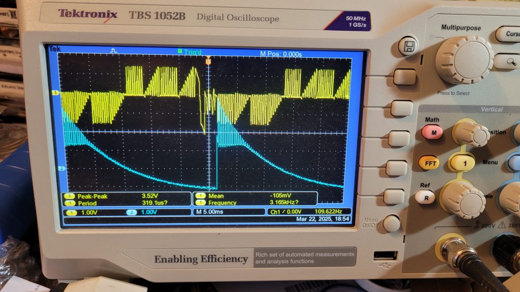
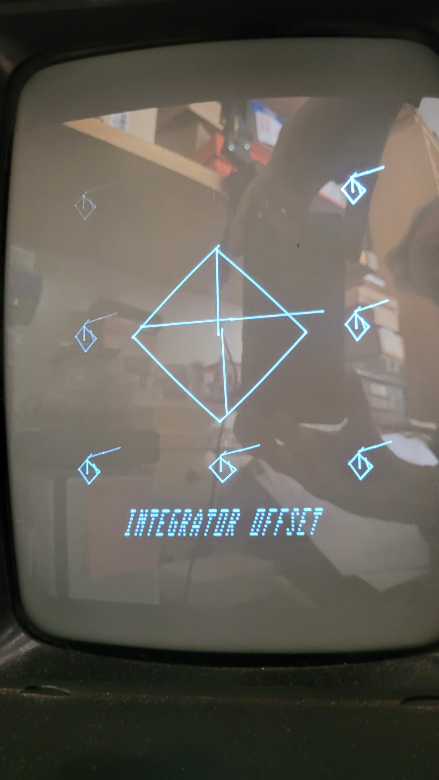
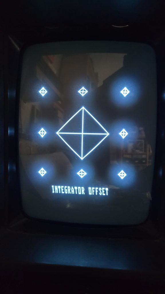
I’d noticed some of the polystyrene capacitors fitted were 4700pF instead of 10000pF as stated in the circuit diagram. I replaced the three 4700pF caps C304,305,306 with 10000pF and the Z-axis (intensity) improved allowing correct display of the INTEGRATOR OFFSET text.
The long tails still failed to align. I tried replacing the remaining polystyrene capacitors but this did not solve the problem.
I found by touching the plastic case of each capacitor in turn the vectors moved back and forth (see video below) — don’t attempt this unless you are experienced in working with live chassis. With the integrator test pattern the lines moved closer to alignment when touching one of the caps.
0v Reference
Fault: long tail vectors
Although the DAC and op-amp replacement had improved the vectors the long tails persisted. Puzzled by the interference I noticed when touching the polystyrene capacitors I took a closer look at the video waveforms for the X & Y axis as below. I wondered how the 50Hz modulation from the capacitor case would affect the signals.
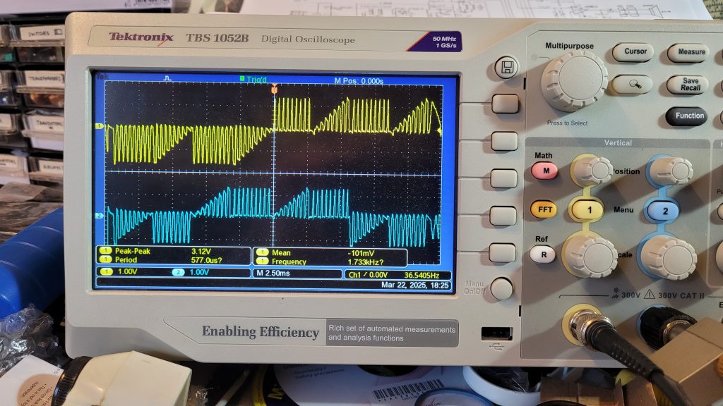
This image shows the X & Y waveforms with the cross hatch test pattern displayed while touching the polystyrene capacitors. There was no evidence of the 50Hz mains hum that appeared to modulate the Vectrex display. Somehow both X & Y axis were affected. The modulation was most obvious on C305 which provides the sample & hold for the Ov reference to both axis. This was a key clue to the fault.
Looking at the circuit there’s no resistor to tie the X & Y axis non-inverting input to ground so it’s effectively very high impedance + input to the J-FET op-amps, IC303. As the circuit board had years of dust and debris I reasoned there could be leakage affecting these reference inputs. So I tried adding a 3k3 resistor across C305 to see if it helped reduce the interference and video tails.
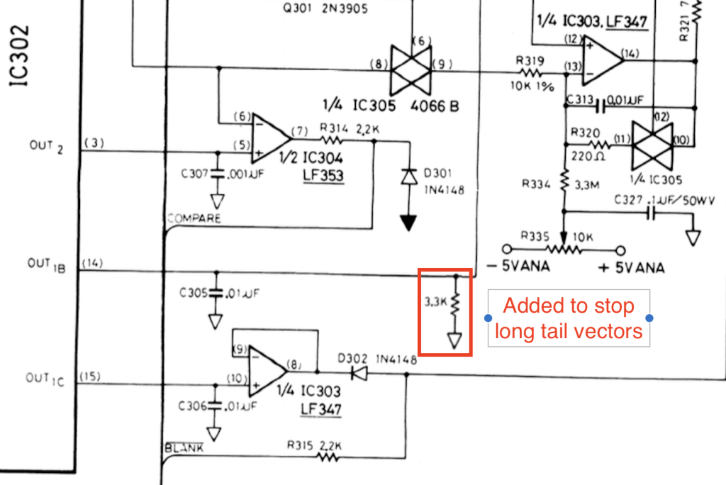
It did! In fact, the resistor enabled correct setting for the integrator offset test pattern as below. The long tails had vanished.
If your Vectrex suffers from similar strange video behaviour maybe the extra resistor will help too. Given I replaced all components between the digital to analogue convertor and the Ov reference inputs I can only think the fault was caused by some conductive paths on the PCB.
I’d tried cleaning the areas around IC303 with isopropyl alcohol but the existing IC holder prevented cleaning beneath and the analogue switch IC305 is soldered in place so again hard to clean. Removing the PCB and placing in an ultrasonic bath may resolve the fault without the resistor hack but I didn’t have the facilities for that size PCB.
Dim Screen when powering up
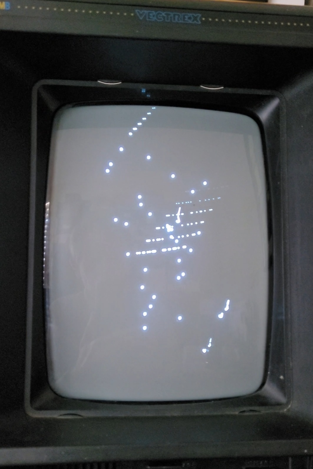
There was one remaining fault with this Vectrex which I failed to fully resolve. The CRT display was too dark when first powering up the Vectrex and became lighter after 10-15 minutes.
All voltages on the CRT’s base were stable although measured higher than the manual states. Voltages:
170v = 162v (160 after 30 mins), 50v = 61v, -30v = -37v
I’d replaced the usual electrolytic capacitors C507, 508 and C516 as suggested by Console 5 – see links below. I’d also replaced C513, a 1000uF 25v with a 35v rated capacitor but there was no real improvement. I don’t have an EHT meter to check if the 5.6Kv was stable, so this could be responsible although I suspect the Samsung CRT may be to blame for the slow warm up..
If you have any ideas please post a comment below.
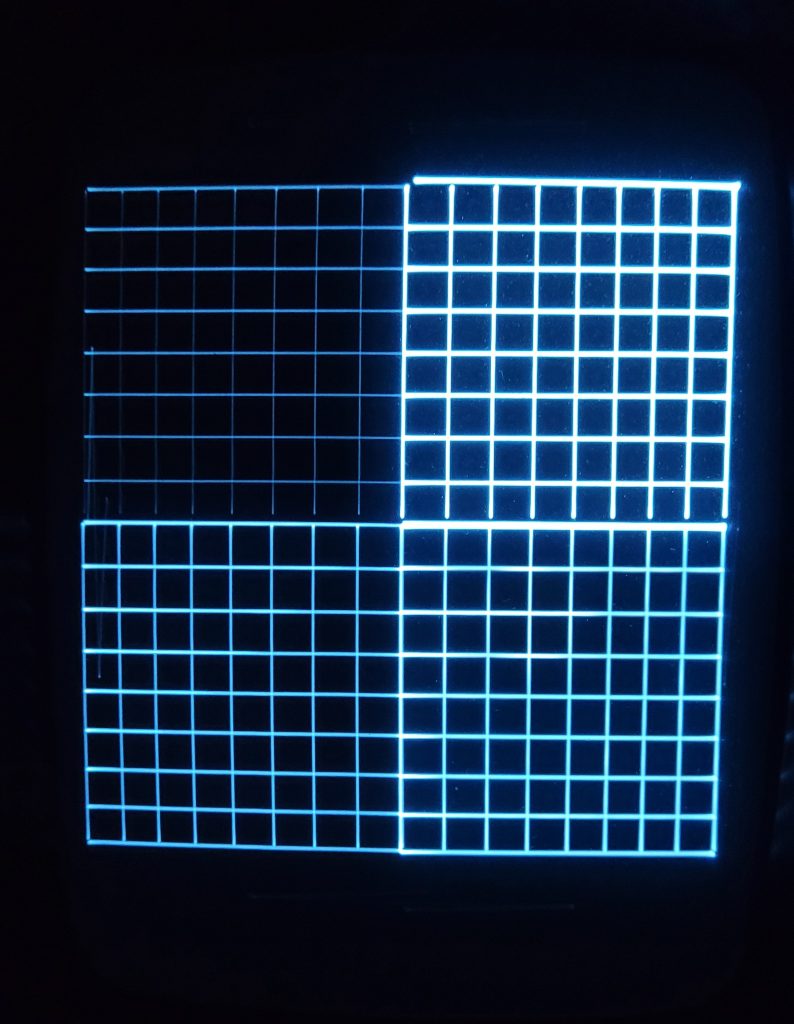
Note in the screen above, the crosshatch test pattern was taken before the 3k3 resistor modification so shows some misalignment.
Useful links
- Vectrex Wiki Console 5 – https://wiki.console5.com/wiki/Vectrex
- Vectrex Service Manual – https://wiki.console5.com/tw/images/a/a7/Vectrex-Service_Manual.pdf
- Vectrex Troubleshooting guide – https://wiki.console5.com/tw/images/f/f8/Vectrex-Troubleshooting_Guide.pdf
- UK Vectrex Fan Site – http://vectrex.co.uk (not HTTPS)
- Vectrex Hackaday – https://hackaday.com/tag/vectrex/
- Scopetrex – https://www.retrorgb.com/the-scopetrex-play-vectrex-games-on-an-oscilloscope.html
Leave a Reply