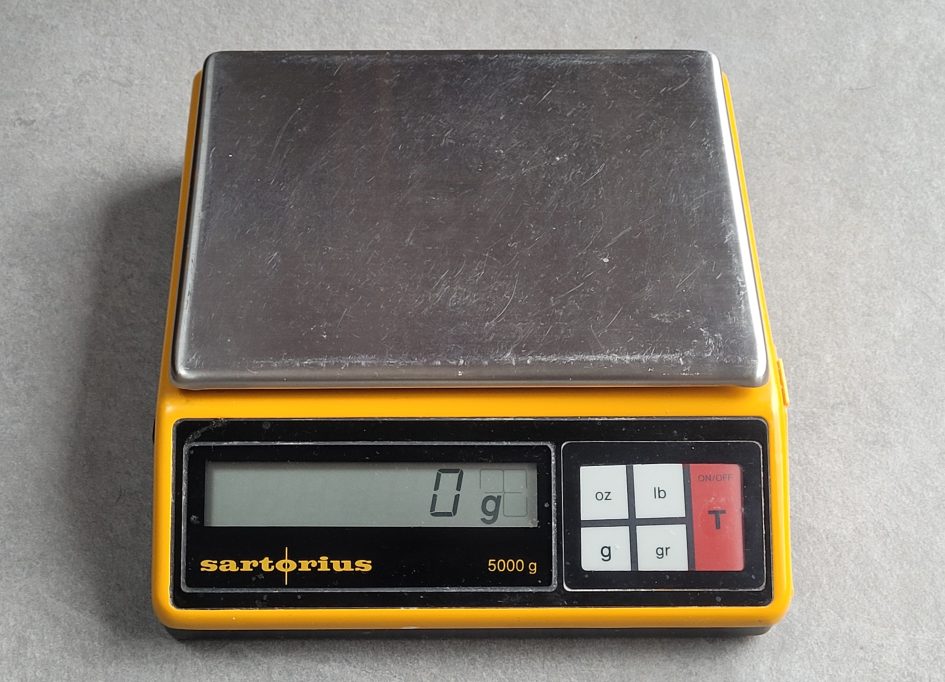
Do you have a Sartorius Toploader 1006 MP9 electronic balance that displays an increasing weight with nothing on it? Maybe it races up to 60 grams or more after switch on and just keeps drifting? If your Sartorius has these kinds of fault there maybe a simple fix to get it working again.
If you’re in a hurry and want to try one remedy then skip to the fix summary below. But before jumping in to the details here’s some details about the fault and background to help understand how these balances work and how sensitive the electronics are to component aging.
It’s taken me a while to repair this Sartorius Toploader that had been in our kitchen used almost daily since the mid nineties and relegated in 2018 when it failed to switch on. I recall taking a ‘Quick Look’, replacing the faulty on/off power switch only to find the display kept drifting. We had to keep hitting the tare button when weighing out ingredients and finally gave up using it.
Fortunately we had a spare Sartorius 1006 MP9 that we’d inherited and that replaced my wife’s original toploader as our the daily workhorse. Nowadays electronic balances that measure 0-5kg with 1g accuracy are commonplace and quite cheap. But the Sartorius 1006 was an entry level lab balance built for daily use. I have to admit I have a soft spot for Sartorius balances and a good reason so keep these balances . My father worked for the company’s UK division in the 80s and we’d been given the 1006 MP9 as a present when he retired.
Stain gauge balances
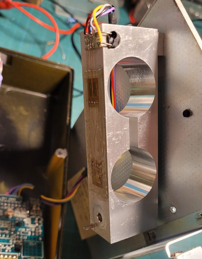
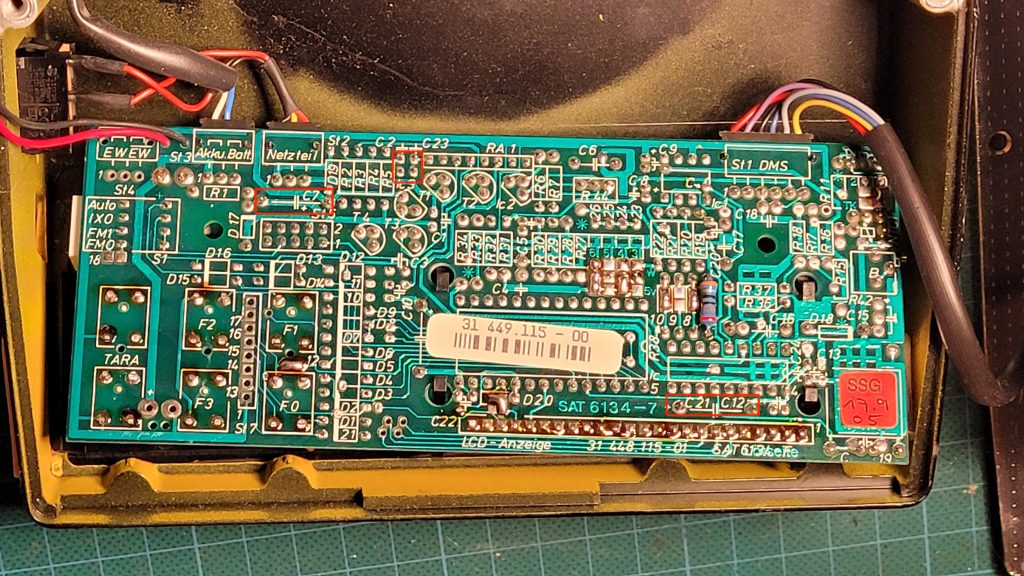
Inside the 1006 MP9 you will find a chunky aluminium bar mount to which the top pan is attached through a hole in the base. You will need to remove the small round black plastic cover underneath to unscrew the hex head fixing which attaches the pan to the strain gauge mount. Also remove the pair of slot head fixings which attach the base plate to gain access inside.
After removing the two screws which hold the PCB in place, it’s possible to reattach the pan and operate the balance with the casing upside down, keeping the base and top pan open. I used a 9v bench power supply but you could also attach a 9v battery.
Take care not to damage the strain gauges which are glued to the top of the aluminium mounts – see above. There are a pair of gauges one above each circular aperture in the aluminium bar. The strain gauges measure the expansion in the aluminium lever which results in small change in resistance. They are configured in a Wheatstone bridge.
Notice there’s a small hole beneath the connection strip which contains an NTC thermistor for temperature compensation. There’s a similar thermistor mounted on the PCB.
Drift fault and causes
Both our Sartorius Toploaders exhibited similar faults. After switching on from cold, the display would steadily increase until it read 50-80 grams. On some occasions, when very cold, the readings could increase to over 400g after a couple of minutes. If left on, although the balance would enter a power saving – – – display, it could be tared to zero and keep relatively constant after warming up.
As the drift fault seemed to be temperature dependent, my first thought was to investigate the balance’s temperature compensation circuitry. I used a freezer spray from an aerosol with a fine tube to apply cooling directly to target components. As mentioned, there’s a NTC thermistor on one side of the PCB and another hidden at one end of the aluminium strain gauge mount.
Cooling the thermistors resulted in reversing the drift error but it soon returned as the devices regained ambient temperature. I found similar behaviour cooling the Op-Amp IC1. (Note the schematic and service manual seems to have 100 added to the component reference numbers, so IC1 on the PCB is shown as IC101 on the schematic.)
Op amp temperature drift appeared to be a problem. The PMI OP 07 DP fitted to our Toploader displayed considerable drift as it cooled and returned to ambient. Unfortunately the IC is soldered directly into the PCB which has plated through holes. This make it tricky to change without a vacuum solder station.
Fortunately I didn’t jump into swapping out the op amp. The service manual details the offset voltage should be between -60mV and -120mV. for normal operation… I measured 50mV so I changed solder link 6 to adjust the offset to bring it in to the correct range. This reduced the switch on drift but the display still kept increasing from cold.
I found an 8 pin IC socket and was just about to remove the OP 07 when I stumbled on the circuit diagram which my father had kept a copy in one of the balance’s boxes.
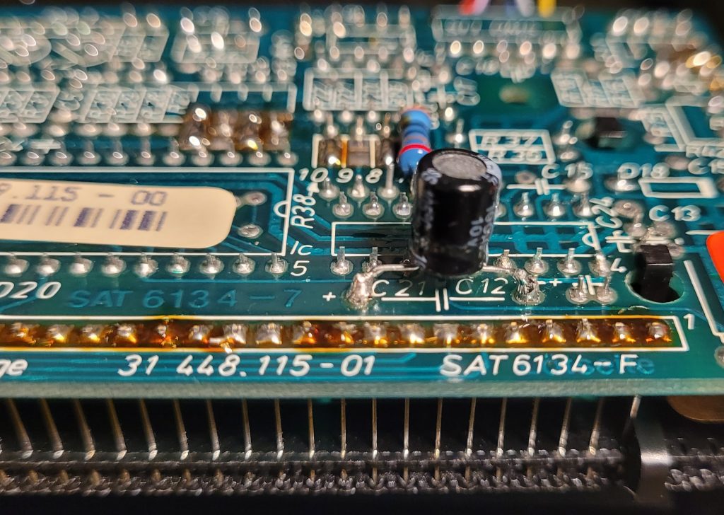
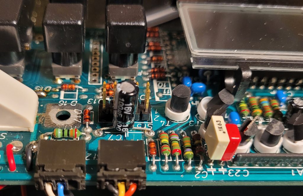
I noticed the op amp uses a negative voltage supply along with the +5v positive supply. This improves common mode rejection and allows the op amp to reach 0v rather than start with a larger positive offset that would occur if it had a single +5v supply. The negative supply measured only -3.7v so I suspected C21, an 100uF electrolytic capacitor. This showed a high ESR, so I soldered a new 100uF capacitor across the suspect component. C21 is housed under the LCD display, so not easily accessible without bending / removing the LCD.
C21 made little difference to the drift and thought it a red herring although I should have persisted, as I found out later. But I noticed a 100nF ceramic capacitor, C2, in series with a 2.2MΩ resistor on the schematic – a suspect component if it had developed leakage. I reached for the freezer and cooled the ceramic. The display showed a sudden shift negative then steadied to hover around zero!
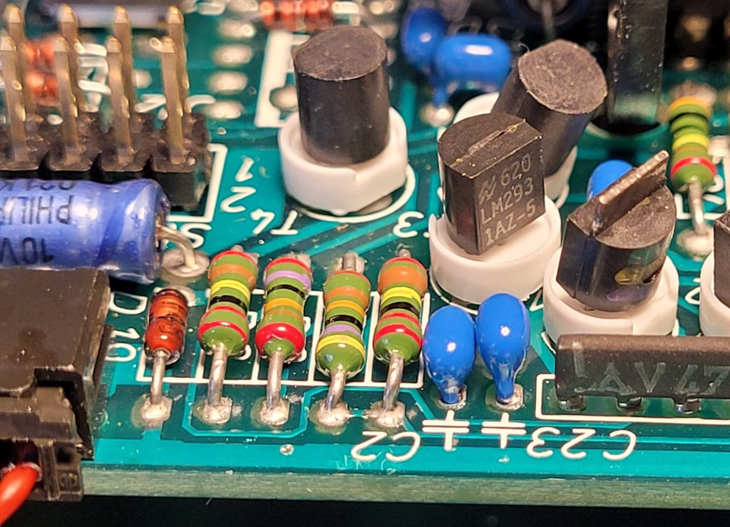
I’d come across similar leaky ceramic capacitors some of which has even become a short circuit. But this component – a miniature blue device – was clearly temperature sensitive which is often the case with low voltage ceramics. I unsoldered the suspect device and replaced it with a small polyester type.
This reduced the drift to around 12 grams over a minute instead of over 50, still not perfect. I reapplied the freezer to my replacement and it was stable. But an identical 100nF, C23, adjacent, responded to cooling just as C2 had. Replacing C23 with another miniature polyester type appeared to solve the drift.
I reassembled the PCB and restored the base with stain gauge into the casing. A final bench test to check accuracy looked good. I returned the Sartorius to the kitchen ready for breakfast prep next day.
The morning after…
To my dismay when I powered up the balance next morning the display started to slowly count up as though ingredients were being poured into the empty dish! Back to the bench.
The fault was clearly temperature dependent. Over night the balance had cooled down in our kitchen and after 5 or so minutes being left on and pressing tare, the display would stabilise. To try and discover what was causing the drift I hooked up a 4 digit DVM to the supply lines to see if there was any correlation between the weight display.
I found the +5v supply varied between 5.000 and 4.883 during warm up as the display changed from 0g to over 100g. A 17mV change had a dramatic effect on zero. The strain gauge only changes a few millivolts so temperature changes can be significant. Sure enough, freezer applied to IC3, the 5v regulator, showed a repeatable correlation: on cooling, the voltage increased and the display showed negative weight then slowly returned to 0g as the voltage decreased as the chip warmed.
I kept looking at another blue Philips capacitor close by to the power supply components and realised it was connected to the 5v rail – see suspect capacitor above. Doh, why had I not replaced it just as I’d done for the -ve supply? I found another capacitor and tacked it across the Philips electrolytic and powered up the Toploader. It displayed 0g. No drift, just the odd +/- as it stabilised.
These Philips / Mullard blue axial electrolytic capacitors have featured in several of my blog posts in which they cause various fault conditions. In hindsight these should be the first components to replace and I recommend you do this first. This will reduce supply line interference that obviously plagues sensitive circuitry like the OP 07 which is comparing a few millivolts.
So I suggest if you have a drifting Sartorius balance from the 1980s with its original blue Philips electrolytic capacitors and miniature ceramic capacitors, replace them with modern alternatives. Polycarbonate capacitors have much lower temperate dependent leakage and should help restore your balance and sanity!
I applied the same remedies to our second Toploader with the same result – a stable display from cold. When removed, I measured ESR readings of over 10Ω for both Philips axial electrolytics.
Fix summary
These are the components causing the display count drift with no weight present. Note the component reference numbers are as shown on the PCB and typically may differ from those depicted in the schematic. Try replacing the electrolytics before attempting the ceramics.
- 5v Supply – replace blue Philips 100µF capacitor, C7, with a 16v electrolytic. Best use a low ESR type (<0.5Ω).
- -4v supply – replace blue Philips 100µF capacitor, C21, with 16v electrolytic. Best use a low ESR type (<0.5Ω). As the existing capacitor is located beneath the LCD module I added a capacitor on the solder side.
- Replace blue ceramic 100nF capacitor, C2, with a 100nF polyester type. Note the existing component is miniature with 0.1″ pitch leads.
- Replace blue ceramic 100nF capacitor, C23, with a 100nF polyester type.
Hopefully if you are reading this it will help fix your Sartorius Toploader balance. If not please leave a comment. I have various spare parts for these balances so if you need anything specific DM me. These balances are well worth repairing.
28/04/2026 at 7:07 pm
Hi,
just letting you know this helped me fix the drift on my 1006MP9 which I had for years 🙂
Many thanks for documenting this!
28/04/2026 at 8:30 pm
Hi Fabian, thank you for the feedback, good to know it’s helped. My wife had been complaining about our Toploader drifting and it’s now back in daily use – an excellent balance running on rechargeable batteries.