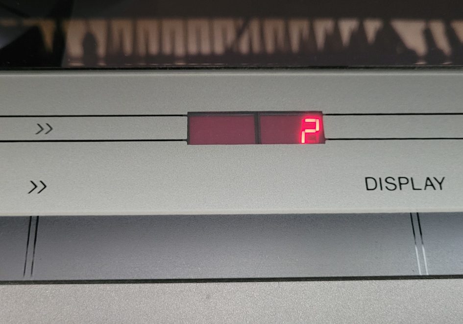
Has your Beogram CD 3300 stopped playing discs? Maybe it starts running for a few seconds and then displays a red question mark instead of a track number? Is so, it could be easy to repair.
Warning: Disconnect mains power before attempting to access the internal circuitry. Dangerous voltages are exposed laser radiation can cause injury if the unit is powered with the case removed.
There are several common faults that affect the Philips CDM mechanisms Bang and Olufsen used inside their 80s CD players. I covered one such fault in BeoCenter 9000 CD Fault.
This post shows you where the suspect capacitor is located and how to replace the component with minimum effort. I’ll assume you have cleaned the lens, tried several CDs and the fault persists so the fault is most likely due to this usual suspect!
You will need a small Torx driver bit to remove the fixings along with a soldering iron, solder sucker or copper braid and small flat bladed screw driver.
Suspect capacitor
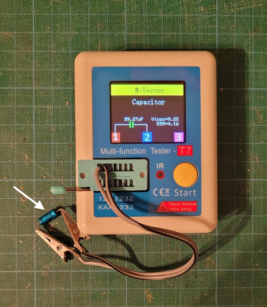
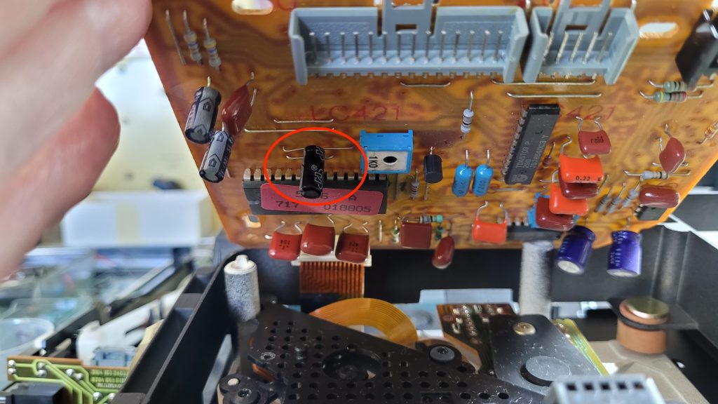
The CDM-2/10 drive and servo board manufactured by Philips uses their blue axial electrolytic capacitors that are prone to failure after 30 plus years. Many aluminium electrolytic capacitors suffer from electrolyte leakage, causing them to dry out and suffer from high series resistance. This 33µF device seems susceptible to failure and may be due to the higher pulse currents it’s subjected to in operation.
The Philips original I removed had a high ESR of over 4Ω which was causing the laser drive fault, even though its capacitance measured a healthy 40µF. There is no evidence of leakage under the PCB where it was mounted. The high Vloss of 9% is another clue the capacitor has aged.
Servo Board Access
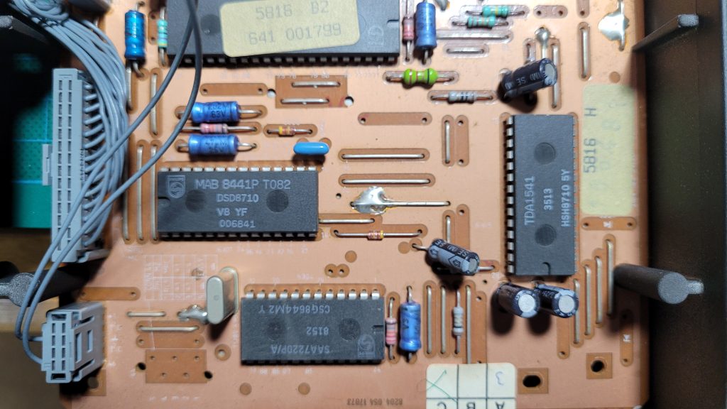
Access to the CDM servo board, where the suspect capacitor is located, first requires removal of the multiple screws from the base. There’s no need to undo the rear fixing which holds a cover in place.
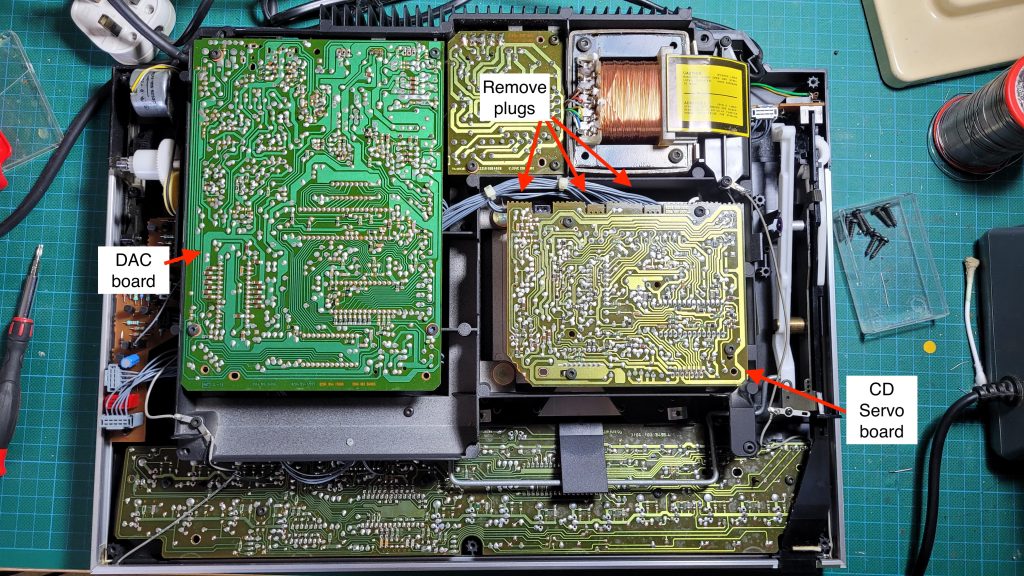
With the base removed, you can see the CD servo board below the mains transformer as indicated below. I found it possible to remove the suspect electrolytic without taking the CDM-2/10 apart. To do this I unscrewed the PCB’s 4 Torx fixings and gently levered the three plugs, shown in the photo, to pull them free. Be very careful not to damage the ribbon cable opposite the plugs on the servo board. With the grey cables clear you can tilt the PCB to see the blue axial capacitor and locate the top connections to unsolder.
I marked each connection with a dot from a felt tip and replaced one fixing to anchor the board while I unsoldered the capacitor. This avoids any strain on the ribbon cable. The capacitor leads were bent over on my PCB, so once the solder was removed I used a small flat screwdriver to gently lift each lead to make it easy to pull free. Take care not to damage the copper pads so apply soldering iron to heat the lead as you lift each wire.
Why not remove the ribbon cable and free the board to work on? Well that requires removal of the upper PCB assembly to access and remove 4 circlips that hold the CDM in place. A bit like removing the engine to change a spark plug…
Replacement capacitor
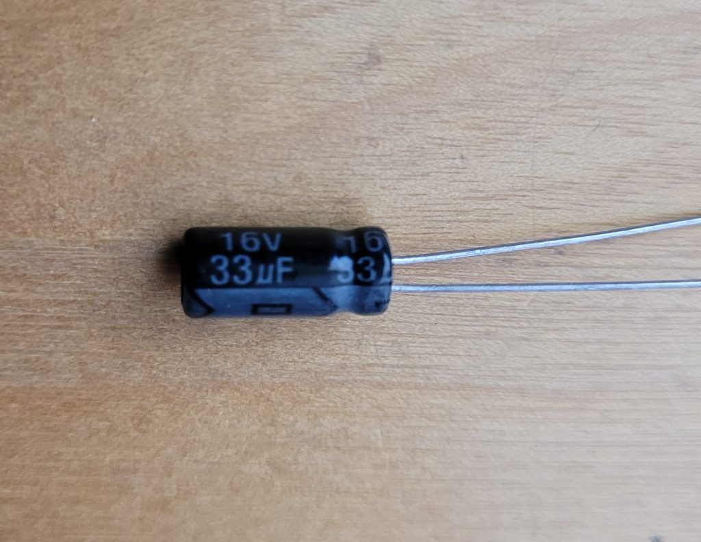
Replacement 33µF 16 or 25v electrolytic capacitors are readily available but finding one with axial leads can be more difficult. A radial lead replacement are more common and can be fitted if you can’t locate an axial part. You may read other forums suggesting low ESR capacitors are not suitable but I’ve found one with an ESR of 0.5 – 0.8Ω works well.
I selected a radial electrolytic with a height similar to others fitted so it cleared lower plate as shown.
Capacitor kits
You may see capacitor kits available containing all the servo board electrolytics, with recommendations to replace every cap. I prefer to check the values first as it may be unnecessary and too easy to damage the PCB copper tracks when removing the old devices. Some PCBs have very thin copper pads that separate from the board when the connection is unsoldered so minimal heat and disturbance is best.
I measured the remaining servo board electrolytic capacitors, two 220µF and two 47µF – radial types – and all were within spec, so I left these in place.
DAC board
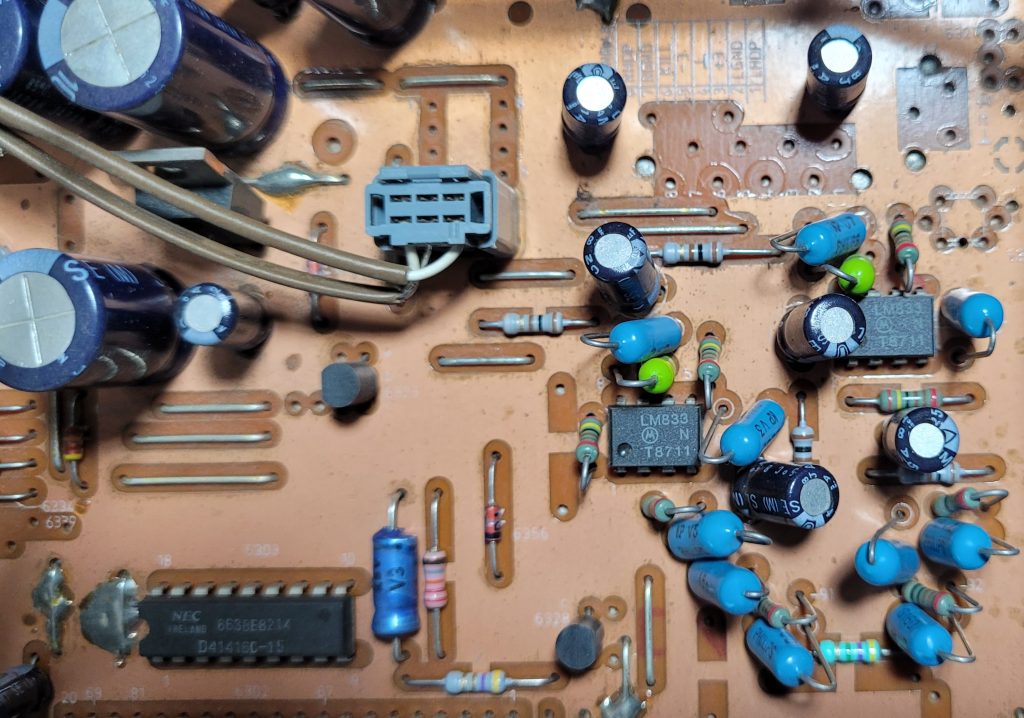
The digital to analogue board, which uses the acclaimed 16 bit TDA1541, also uses several blue Philips axial capacitors along with the usual black radial types. It’s tempting to replace all the blue ones, just in case, given the servo board failure. I checked the values and again all were well within specification so I left them in place so I can monitor.
If I was servicing the Beogram for a client I would probably replace all the blue axial capacitors due to reliability concerns and reduce risk of further problems. Replacements don’t have to be axial – as you can see higher radials are also fitted as standard. Most of the blue capacitors are used for DC decoupling so don’t require an audio rating so it’s curious why B&O chose the Philips parts. (The black and grey cased radials are not Philips components as far as I can see.)
If you do replace the blue axials with radial types be carful with bending the wires close to the PCB as there’s a bare copper screen top side as shown above.
Audio rated capacitors
The Philips blue can series were very popular in the seventies and eighties and used in many audio applications. Along with their C280 ‘tropical fish’ polyester capacitors they found their way into many hifi audio amplifiers. I made frequent use of them.
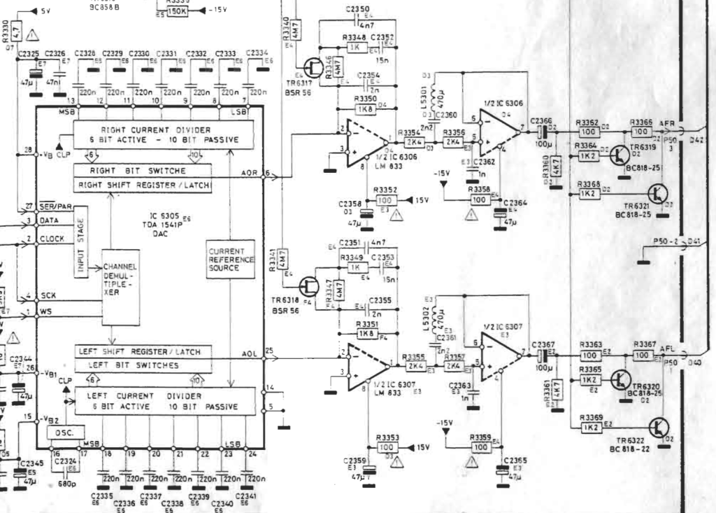
Audio quality components should be sought for all electrolytic capacitors in an audio signal path such as the 100µF DC blocking capacitors C2366 and C2367, rather than basic low ESR DC decoupling types.
Note in my Beogram neither C2366 or C2367 appeared to be bipolar types although the circuit below shows the LM833 op amps have +/- 15v supplies suggesting the capacitor’s positive terminal can swing negative which is not good for a standard polarised electrolytic.
Listening tests
With the suspect capacitor replaced the Beogram plays CDs again without any problems. Sound quality via its matching Beomaster 3300 paired to the newly refurbished CX100s is very good.
I will take another look at the question of bipolar audio coupling capacitors in another post. Meanwhile if any readers have thoughts on this please leave a comment.
Leave a Reply