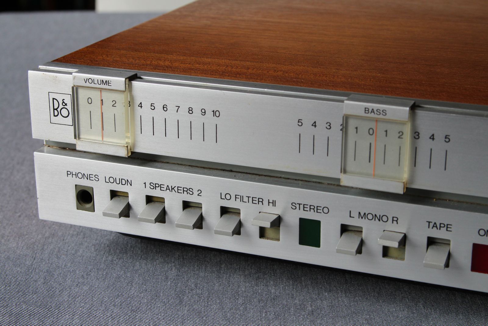
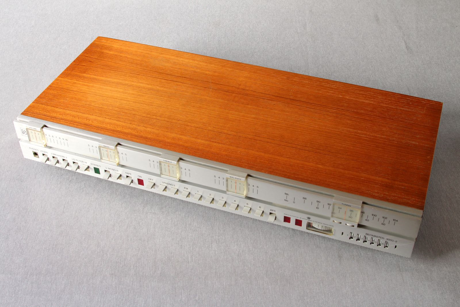
 This iconic Bang & Olufsen Beomaster 3000-2 amplifier / tuner was manufactured in the seventies. Designed by Jacob Jensen the 3000-2 is a solid design with aluminium front panel and solid teak enclosure. Cabinet is solid teak and front panel is solid aluminium both in very good condition with all sliders complete and smooth.
This example has been serviced and the usual aged components that fail have been replaced so the unit is in fully working order and sounds excellent. There is a very faint mechanical hum from the transformer which is common on these models but can’t be heard via the loudspeakers. There are two phono / DIN sockets with RIAA equalisation for vinyl record decks along with tape input and output. The FM tuner has manual tuning and 6 preset channels. Two sets of loudspeakers are supported along with headphone output. The impressive range of switches include high and low pass filters, loudness and AFC for the FM radio. All the panel lights work as intended for stereo, on and fine tuning.
Dimensions: width 58cm, height 9.5cm, depth 26cm. Weight is 8.5kg.
A classic Beomaster that is highly collectable and still very usable today.
If you have a faulty Beomaster 3000, Beomaster 3000-2 or Beomaster 4000 check the common faults post which has several suggestions to fix common problems.


08/01/2017 at 7:18 am
I have an BEOMASTER 3000-2 and it works good except one of the toggle switches wont stay down for the speakers to come on… is there some place i can have this repaired?
thank you
Curtis
08/01/2017 at 12:27 pm
Hi Curtis – the toggle switches can become stiff and freed up using aerosol switch cleaner so a repair should be possible. There are two speaker toggle switches (1 Speaker 2) so you could use either set to drive a pair of speakers. Which toggle switch won’t stay down? If it’s one of 9 input switches that are interlinked with the Off then it might be the main power switch that’s stiff and won’t click on. It’s possible a repair shop can use switch cleaner to get it working again but finding a replacement switch assembly is near impossible. It’s a messy job as you need to get lots of cleaner inside the mechanism and keep operating the switches rapidly to get it to loosen up. Try googling vintage hifi repair shop to see if there’s anyone in your area. Good luck it’s worth trying.
31/12/2019 at 12:22 am
I´am afraid its to late for lubrication, the underlying hook/plastic has broken.
This is a big job, the whole switch assy has to be taken down, the switchpart
removed and the plastic part repaired, sometimes with drilling in a small pin
or refurbishing a new plastic part. If you are lucky, the spring fixture is broken.
This is one of the hardest repair jobs on these units.
Allways replace the two rectifiers, they will fail and cause all sorts of trouble,
such as humming transformers, tuner instability etc. (measure at load, y´ll see)
22/01/2020 at 9:15 pm
Thanks for your feedback Carl. Agree replacing the bridge rectifier, especially after the reservoir capacitors have failed, makes sense. I prefer to test components first rather than just replace – as you say measure at load, I use a ‘scope to look at ripple and see if it’s even on both phases. If you can’t do this or repairing for resale then replacing ‘the usual suspects’ should prevent failures from years of surges!
13/03/2020 at 12:19 am
I just have got one if these beauties. Essentialy it works, of course, the switches need some cleaning. But I have noticed once it gets hot under load, the main transformer starts to resonate very loudly, literary like a high voltage fuse box. What may be the cause and what may be a fix?
Thank you.
Marko
13/03/2020 at 7:23 am
Hi Marko – see the post on B&O Beomaster 3000 Faults. Unfortunately it’s a common problem. The transformer laminations rust and vibrate which causes the mechanical hum. Only fix is to replace the transformer. You could try replacing the 3 large capacitors if they look original as they can cause excessive load on the transformer and bridge rectifiers when they fail at this age. See the post for more details.
09/10/2020 at 8:36 pm
Hi there, I have just acquired one of these in amazing condition. Great amp, but the radio tuning struggles to hold onto any stations without a lot of hiss. My question is, should there be an aerial at the back? I’ve not been able to get a manual, so can’t easily check
10/10/2020 at 7:14 am
Hi Alan – yes the Beomaster 3000-2 needs an FM aerial, there are two sockets on the back panel for different types, both on the far left. There was an optional TV style aerial that clipped on the back and plugged in one of the sockets. You can attach a standard FM dipole to the coax socket marked 60-75 ohm or a folded dipole to the pair marked 300 ohm. It’s a nice analogue design. As a test you can try a 1m length of wire in the centre of the coax socket and it should pull in some stations.
19/10/2025 at 7:05 pm
Do you have old house with lead paint it’s holding out the reception i like my answer better but then i know nothing about these things i have one i want to sell but dont even know what to ask for it it was my dads in the seventies he kept all his stereo stuff he has it all and all the albums every cool album there was buy this thing from me
19/10/2025 at 10:07 pm
Haha, I like your conspiracy theory about lead paint. One best left on Facebook. Some will ask over £400 for a working Beomaster 3000-2 while others may want a little over £40. If it’s been untouched and un loved since the 70s it will require replacement of the electrolytic capacitors as mentioned in the posts and comment threads here. This can cost several hundred pounds, hence the price for serviced models. The mains transformer is also prone to hum loudly as the potting compound ages and this can affect resale value. I have no need of another Beomaster but if any visitors are interested I’ll DM you with details. Please don’t throw it away, put an ad on Gumtree or eBay where you can sell for free.
07/03/2022 at 5:10 pm
Hi. I wonder if anybody can help. Can I connect a second pair of speakers to the beomaster 3000-2 without risking the amp? I have a beovox s45-2 connected to speakers 1, they indicate 4-8 ohms. I don’t know if the second set is in series or parallel mounted. Thank you in advance! Regards José Armindo
07/03/2022 at 5:36 pm
Hi José, the user manual states it can handle 2 pairs of 4ohm speakers and they can be operated together by depressing both speaker switches. There’s a schematic of the output stage showing the switch wiring in my post https://storycase.co.uk/radio/bang-olufsen/bo-beomaster-3000-faults/
As the amplifier uses capacitor coupling for the speakers, operating two sets of 4-8 ohm speakers in parallel should be fine.
Hope this helps.
23/07/2022 at 2:07 pm
Hi, I have just purchased a 3000-2 with a pair of huge matching speakers in auction and they are all in their original B and O boxes.
So tomorrow is the test when i switch it on – cross fingers all please.
24/07/2022 at 1:46 pm
Nice kit to own and keep using. Hopefully all will work fine and the foam speaker surrounds have not split – plenty of suggestions here is you find any issues.
26/10/2022 at 3:11 pm
Hi is it possible to have vinyl decks with photo rca and a tape deco with phono rca connected at same time? Please wb
27/10/2022 at 1:00 pm
There are separate RCA phono inputs for two decks and a tape input and output on the 3000-2. So you can connect all at the same time but only one deck will play and record at any one time depending on which you select from the front panel.
03/07/2023 at 2:28 pm
I don’t know if this is still open, but I’ll give it a try.
I have one of these units that plays very well on my Beovox S45-2. Amazing sound! Tape input works well and FM as well (though I have bad reception in general where the unit is used). But now I have tried connecting my Project P1 turntable to both turntable inputs using both phono and DIN inputs. But I get a loud hum. I have tried connecting the turntable to an external preamp and connecting the input to the tape in and that sounds terrific as well.
So to me that points to the RIAA, or? What could I look for and where do I find it?
Thanks in advance!
03/07/2023 at 6:34 pm
Hi Frank, sounds like the RIAA preamp – you are using phono input 1 for magnetic cartridges? There are some things you can try. First is there an earth Loop. Disconnect all external inputs, switch to phono 1 and turn up the volume slowly. Does it hum? If not, connect the P1 and check for hum again. If the 3000-2 hums with or without the P1 it’s probably the 250uF electrolytic caps on the preamp board. The 50K skeleton preset pots can also go open circuit so try adjusting from beneath noting their positions first.
If there’s hum when you plug in an external input check the units earth connection or if two pin continental plug sometimes reversing the plug can reduce hum by swapping live, neutral. Most modern devices are double isolated no earth but mention just in case as it can catch you out with Phono inputs on turntables that have separate earth connections. The preamp pcb is accessed from underneath I think.
Also check if the P1 cartridge is a low output moving coil type eg Ortofon as the 3000-2 preamp only works with higher output moving magnet types. Your separate RIAA preamp may handle both.
16/07/2023 at 9:07 am
Thanks Rick
Well it only hums when the P1 is connected. And the cartridge indeed is a modern Ortofon one, I’m not quite sure which, but MC. I have been trying to find a users manual online for the 3000-2 with no luck as I was curious about the difference between phono 1 and 2.
It seems like I have to find a vintage Beogram for my setup as well …
16/07/2023 at 7:24 pm
Some vintage Beograms have an RIAA preamp built in see – https://beoworld.org/article_view.asp?id=67. You mentioned an external preamp – did you try Pro-ject’s MM/MC Phono preamp https://www.project-audio.com/en/product/phono-box/ – this supports both high and low output MC cartridges. As the Photo Box has RIAA you would need to use the tape input as you mentioned. Alternatively you could look for a MC preamp that just boosts the signal without equalisation to feed the higher output P1. This allows you to use the phono input instead of tape.
11/11/2023 at 11:23 am
My Beomaster 3000-2 recieves stereo FM but the stereo light doesn’t burn. I replaced the broken one and if on Phono or tape the light burns but not on FM. Signal indicator is on 4 or above and on headphone there is stereo.
Can you help?
11/11/2023 at 4:55 pm
Sound like a wiring fault. Use the Beomaster’s circuit diagram – the FM stereo lamp is switched on when TR22 detects the 19KHz pilot tone. The detection level is set by the zener ZF18 (18v). So check there’s at least 600mV on the base of TR22 with a stereo broadcast and same for its collector. This provides the lamp with ~12v as TR22 is switched hard on to ground. Follow the voltages back to the lamp and check the wiring. Possible a previous repair has mixed up the lamp wiring connections.
Let us know how you get on.
23/11/2023 at 7:25 pm
Hi. Rick
I have exactly the same problem, the 2 red stereo light does not come on at all, the bulbs are fine.
Have checked the base of TR22 and there is no voltage same as emiter..Collector is 12.77V
Would you point me where to check next.
Thank you.
23/11/2023 at 9:41 pm
Hi David, check the voltages around TR20 – collector should be ~14v, base ~1.2v, emitter 0.7v. Check the 15uF electrolytic on the base of TR22 it could be leaky – it’s the reservoir smoothing for the 38KHz rectification. If you have an oscilloscope, check the 19Khz pilot tone 9v peak-to-peak on TR20’s collector. TR19 and TR20 both amplify the 19KHz signal from just 70mV pp on base of TR19 so following the path through to where it’s rectified by the ZF18 zener should help identify where the fault is.
24/11/2023 at 6:12 pm
Hello Rick.
Thank you for swift reply
TR20 collector is 15.75 base is 1.4 and emiter is 0.75v. I have soldered a new capacitor on the base of TR22 in my case it was 22/40.
Unfortunately have no oscilioscop.
Tested TR 21 and base is 1.966v emiter 1.973v collector is 16.57v. Not sure what to do next.
24/11/2023 at 9:59 pm
Given the voltages around TR20 and TR21 seem okay, check the voltage across the zener ZF18 – if there’s at least 17.5v on its cathode and still 0v on the base of TR22 the zener is probably faulty. TR21 is biased off as the emitter is higher potential that its base – this is due to TR22 not being switched on and why the stereo light does not illuminate. So replace the zener – if you don’t have one try a 560k resistor in its place which should at least trigger TR22 until you get a zener.
25/11/2023 at 1:11 am
There is 15.67V on the cathode of ZF18 and 0V on the base of TR22.
Soldered in the 560k resistor and now on the base of TR22 there is 0.593mV but still no stero light illuminating. ZF18 is a 0.5w 18V. Could bzx55c18 be installed instead ?
25/11/2023 at 11:32 am
Surprised 0.6v is not sufficient to switch on TR22 – have you tried an ohms check on TR22 to ensure there’s a base – emitter junction – maybe it’s blown. bzx55c18 is good, any small 18v zener should work.
25/11/2023 at 1:57 pm
15.67v on the zener is too low. Just thought if your digital multimeter can measure AC volts you could see what it reads on TR20 collector and the zener’s cathode. The schematic shows 9.6v peak to peak on the collector, but your meter will probably show rms i.e. 9.6 / 2.828. Accuracy depends on the meter as many are designed for low frequency ac i.e. 50/60 Hz and TR20 has 19KHz with 38KHz on the zener! It’s tricky without a scope to check signal levels. The cathode should have 17.5v with 0.5v pp 38KHz (full wave rectified) that reaches the zener’s 18v threshold. So it’s a combination of DC level and ac ripple that switches on TR22.
27/11/2023 at 8:42 pm
Tested the TR22 transisitor and is fine. Its a NPN transistor base to collector and emiter gives ~ .675
The TR20 collector in AC gives 0V the same with zener cathode. Tried using Fluke 77 and a chinese multimeter.
27/11/2023 at 10:36 pm
Does your Fluke measure frequency? You may be able to use it to detect the 19KHz (TR19 & TR20 collector) / 38KHz (zener cathode) tones for the decoder.
27/11/2023 at 8:56 pm
Zeners cathode is 15.61V regardless whether in stereo broadcast or not.
27/11/2023 at 10:31 pm
Okay, seems there’s no 19KHz on TR20 so check TR19 has at least 0.6v base-emitter and 15+v on collector. If so it could be the electrolytics – there are several 10uF in the signal path 174, 175, 176.
28/11/2023 at 2:56 pm
Unfortunately both multimiters don’t do frequencies. There is 16.4V on TR19 collector but 0V on base and emitter.
28/11/2023 at 5:07 pm
Ah ha a clue – TR19 is not biased on so check the 4.7uF cap (181) there should be at least 1v on the + side but could e leaky and low R. If cap is okay, the base voltage is provided by the resistor divider 150k (179) & 12k (180). Check values and for dry joints around these and via the coil 8022012.
28/11/2023 at 10:17 pm
Soldered out th cap and its shows 4.7uF.
the resistors are fine also 180 shows 14k and 179 164k. Resolderd joints on resistors and 8022012 coil.
The 2 red lights still not iluminating. Field strength is 4 enough to trigger the light I guess.
28/11/2023 at 11:04 pm
Oh, the stereo light is green, the two red tuning lights show equal intensity when on tune. If no stereo, check neither left or right mono switches are pressed. The Beomaster needs a reasonably strong signal for stereo so 4 or over should be fine. The red tuning direction lights are driven from the differential pairs TR11,12 & TR14,15 nothing to do with stereo – sorry I mis interpreted your initial question about two red stereo lights. If these are not working check the collector voltages for TR 12&14 – they should be equal on tune around 9v. There’s a 50k preset for intensity – check this has not gone open circuit – I’ve had to replace several presets in 3000-2s the wipers can fall apart over time! Hope you finally fix it.
28/11/2023 at 11:46 pm
Didn’t know how to call them my fault. Actually the green stero light works. TR12 collector shows 4V and TR14 is 16V. Light intensity preset is fine now set to 25k but 162 light balance is 7.2M and cant really adjust it supposed to be 50K also.
29/11/2023 at 9:22 am
Yes, if the light balance pot (162) is reading 7 meg it’s faulty – it’s a 50k. The wiper may just be tarnished solved with switch cleaner but if it’s very loose best replace with a new 47k. TR12 & 14 will read different voltages when not on tune and left / right should indicate which way to move the slider to get equal brightness.
29/11/2023 at 5:02 pm
Hopefully with your help we get it fixed.
I have deslodered the pots for intensity light and the balance. I have checked resistance and they are fine. 50k on both
29/11/2023 at 6:08 pm
Have you checked the resistance at the wiper as you adjust as well as end to end? They can go intermittent – high resistance but measure fine across the fixed ends.
So as I understand the stereo light works but the red tuning lamps are still not working. Does the and stereo decoder work?
30/11/2023 at 12:22 am
Yes. I have tested resistance at the wiper and end to end. Could adjust the resistancei with no issues. Yes that’s correct the green stero light works but red tuning lamps not. How do I test stereo decoder ?
30/11/2023 at 2:21 pm
It’s puzzling. If TR12 collector measures 4v one bulb must illuminate. The +ve supply to TR12 and TR14 is via the filament so if the bulb is blown there would be no voltage reading. The light intensity pot controls the voltage at TR12/14 emitters so the lower it goes the brighter the bulb. It should sit at 3v so there’s 12v across the bulb from a 15v supply. You should be able to check the voltages are correct and collectors both change as you tune in to a station. Measure the voltages directly across each bulb and check they are in place not worked loose from the housing.
If TR14 collector always reads 16v then check the base of TR15 is 5v but setting the light balance pot. If that’s okay check base of TR14 is around 4.4v. If all voltages correspond maybe the bulbs have been replaced with a higher voltage type. Do you know the Beomaster’s history?
Second puzzle is you say the Zener’s cathode is 15.61V regardless whether in stereo broadcast or not. And you say there’s 16.4V on TR19 collector but 0V on base and emitter but the green stereo bulb works. This is odd, so I suggested you check if decoder is working by listening to a programme ideally via headphones so you can hear if it’s actually stereo.
30/11/2023 at 8:17 pm
Its probably like a guiding me a blind man a bit, apologies for the confusion.
The stereo light works when tape or phono buttons are pressed, as soon as FM pressed the light goes off.
The bulbs are fine and they sit tight. I have tried them in the power light socket and they do work so assuming they are correct voltages also.
I have deslodered the both potentiometers for intensity and balance and tested them moving the wiper and checking the resistance and all was fine. I have checked the voltage on the base of TR15 and manged to set it to 5V with balance pot. The base of TR14 reads 4.58
Light intensity pot when adjusted does not change values on TR12/TR14 emitters and they sit both at 4.27.
By accident manged to shortcut metal tops of the two light potentiometers and the tuning bulb with green wire illuminated so cabling must be fine. But maybe this gives a clue also.
01/12/2023 at 2:06 pm
Ha, yes exactly, I’m not asking the right questions. Let’s recap:
1) On FM, neither red tuning bulbs illuminate but the bulbs work. The driver collector voltages are correct (< 4-9v) so the bulbs should have enough voltage across them to work. So check the bulb connectors are not tarnished as it seems the resistance is too high so not enough current (~30mA) to light the bulbs. Check the resistance of the wiring that feeds the +15v to both bulbs maybe that's gone high – dry joint etc. Another way to check is to dab a 120Ω resistor between collector of TR12 or TR14 and ground (0v) to check the bulb lights. You can try the same thing with some croc clip leads directly to the bulb from the +15v supply in series with 120Ω and trace back the wiring.
2) The green stereo lamp also fails to illuminate when tuned into a stereo FM station but does work other inputs. There's no base voltage on TR22, collector at +15v so there's no voltage difference across the bulb in FM stereo. This also disables the decoder so you don't hear stereo. One clue is 16.4V on TR19 collector but 0V on base and emitter so you need to trace back and ensure there's enough voltage at the junction of R179 & R180. You checked the values and 164k & 14k so what voltage is it reading the each side of R179? If one end of R179 has +15v maybe TR19 has gone s/c base emitter?
We will solve it eventually.
01/12/2023 at 4:41 pm
I’m a blind man thanks for guidance.
Yes, all above is correct I measure to the chassis.
The light with green wire
works when tr12 collector touches ground via a 120ohm resistor and TR14 lights the blue wired bulb. There is no voltage on 180 and 179 resistors both ends.
01/12/2023 at 5:50 pm
Didn’t realise you are blind missed the ‘me’ in your previous comment. I will help you, had it not been for Morefields I’d be similar.
Re 1) In circuit, check the resistance to ground/chassis at the emitter of TR13. It should read near <1 ohm. If high resistance try running a wire to chassis and the emitter to check for track / wiring problem. If it reads low and TR13's base is ~0.7v and the collector <4v then replace TR13.
And for 2) In circuit, check the resistance to +15v at both ends of R179. It should be <1 ohm one end and if not could have a broken track feeding the +15v end. So solder another 150k ohm to the + side of C181 (4.7uF) with the other end of the 150k to +15v supply. This should provide around 1v on base of TR19. You could also try running a wire from the +15v supply (+ end of C145 400uF) to the end of R179 not connected to R180. Maybe the +15v supply to this area has failed and is causing the strange faults?
02/12/2023 at 9:15 am
TR13 emitter resistance in circuit is 0.1 ohm to the jumper (black , shwarz, sort marking on the schematics diagram.). The base has no voltage and collector is 4.21V. I have run the wire from Tr13 emitter to chassis but that didn’t lit the the tuning lights.
2) The R179 to +15v at the collector of TR9 is 0.1 ohm and the other side to the positive side of 181 capacitor is the same. Running the wire from C145 to end of R179 that is not connected to R180 Lits the both tuning light.
02/12/2023 at 12:29 pm
Seems the +15v supply wire feeding the PCB has broken or there’s a dry joint or track break.
1) TR13 base needs to be >0.65v – the +15v supply must be missing – is there no voltage either side of R156 22k? If so, this is why the wire for fault 2) fixes the tuning lights. So add a permanent wire from the + end of C145 to the +15v end of R156. This should restore the supply to the PCB and fix the tuning lights.
2) With the wire in place from 1) is there now at least 1v on base of TR19? If so the stereo light should come on as well if tuned in to a strong enough signal. If not follow the voltages through across TR19, 20, 21 and 22 looking for base emitters that are not >0.65v to check in case previous tests have caused a problem.
02/12/2023 at 4:22 pm
With the wire soldered in, on the base of TR19 there is 1.27 V. Voltage is there all the time despite changing the inputs to Tape or Phono. Tuning lights are lit all the time also regardless of wheter in FM input, Tape or phon. When filed strengh
is 1.5 both tuning light are lit, the stereo light is flashing also. But when tuned in to stronger signal there is strong stero light.
02/12/2023 at 4:42 pm
Good, it seems all lights work as intended – does the programme sound in stereo i.e. the decoder is working?
The +15v supply to the tuner is connected all the time on the circuit diagram – it’s not switched when FM is selected – so I’d expect the voltages there all the time eg on TR19. Hopefully stereo broadcasts are being decoded and you’ve fixed the Beomaster.
02/12/2023 at 6:47 pm
listening to the radio now via headphones but can’t work out if it’s in stero or not. Was wondering if pressing Mono switches would change something.
02/12/2023 at 7:52 pm
Yes, the mono switch should change the sound stage to the centre and be noticeable. The stereo lamp on FM indicates the 19KHz stereo pilot tone is being received so the decoder should mix the Left+Right which is broadcast for mono receivers only with the left-right that’s present above the pilot frequency in the 20-38Khz range to produce the separate left and right channels.
02/12/2023 at 8:18 pm
Stereo light stays on when the mono switches are pressed or depressed. Should they be on all the time in FM mode. Can’t here much difference also.
02/12/2023 at 11:42 pm
The user manual says if switching L and R to mono reduces hiss on a stereo programme the signal is not strong enough. It does not mention the stereo lamp though. There’s an ‘M’ connection from the mono switches to the stereo lamp to switch off the lamp for other inputs. Diode 226 prevents the mono switches from affecting the decoder so it seems the stereo light on FM is automatic and dependent on signal strength and programme. Best choose a music programme and guide to listen for true stereo operation. Some programmes just broadcast mono even with a pilot tone so there’s no guarantee the stereo light actually means there’s stereo content.
04/12/2023 at 7:18 pm
Stereo light comes on when tuned into a signal. Thank you very much for you help. Will leave it as it is for now. Im sure someone will find this troubleshooting helpfull.
04/12/2023 at 10:52 pm
Glad to know you have got the stereo and tuning lights to work again. Turned out to be an odd fault and too easy for me to jump to wrong conclusions! Try listening to different programme sources to check the stereo decoder is operating. There may be other parts of the circuit where the +15v supply is missing if the PCB has a crack that was causing the problem. If so check the voltages around TR23 & TR24.
06/12/2023 at 6:55 pm
On some radio stations I do can hear
the difference when switching to mono. On Tr23 and TR24 voltage is almost the same. Base is 1V Emitter is 0.35V and Collector is 7.95V. The Voltage is there when stero light is of also.
06/12/2023 at 9:40 pm
Sounds good, the decoder is working as you can hear a difference. Values are normal, the two channel’s voltages should be within 5-10% of each other and independent of stereo / mono switch as they are just preamplifiers.
06/12/2023 at 10:18 pm
Thats great. Now looking to buy replacement bulbs. The bulb is PH12/30
does 30 stand for 30W or 30 mA ?
They look the same as standard T5 dashboard bulbs easily avilable. Would T5 1.2 W be ok ?
07/12/2023 at 2:18 pm
30=30mA. They need very low wattage ~0.3W. Can you imagine a 30w incandescent bulb in that size 🙂 1.2W requires 4x the current and would be too dim I suspect. See https://www.rapidonline.com/wire-ended-filament-lamps for some options.
12/12/2023 at 9:19 pm
Managed to find them here fishtownsound.com
Just the same as the original.
My next project is beogram 1202 that spins the platter couple of turns and then stops/ jams.
Thank you Rick for your fantastic guidance.
13/12/2023 at 12:18 pm
Brilliant – thanks for finding fishtownsound.com, they have a useful supply so have added their details to Radio Retro Useful links. Guess this is the one you picked Beomaster 1900 2300 2400 compatible lamp bulb kit The Beogram sounds a fun project, probably mechanical, belts good place to start!
11/01/2024 at 4:14 pm
Hello.I have a beomaster 3000.2
My problem is that I can’t adjust the idle.While the pot is in the middle the current begins to high around 0.4 when turning on the amplifier.
Where should I look?
Thanks
11/01/2024 at 11:17 pm
Hi Alexander, first check the wiper joint on PCB for the 250Ω pot is not tarnished and open circuit – it should measure ~125Ω to either end if in the middle – if not replace the pot. Compare with the other channel. If resistance is okay then measure the voltage between the bases of TR44-TR47 (R) or TR59/TR62 (L) it should be nor more than 1.9v (29.2-27.3). Also check the output mid point (+ve end of 3000uF) is ~28v half the supply.
17/01/2024 at 11:17 pm
Hello.The voltage between the two bases are 0.3v.
The trimmer is fine.
While in the left channel i adjust the idle,in right channel i cant get voltage drop in emmiter resistor.It starts with 0.6 mv and goes to zero in a few seconds
Where should i check?
Thanks
18/01/2024 at 9:16 am
Which emitter resistor? The base delta of 0.3v seems too low – compare with the left channel. Best check the output voltage mid point for the right channel and work back to see if any of the driver transistors or diodes have blown. As the fault voltage / current changes in a few seconds it suggests a junction is warming and shutting down – this is why TR45 and the PTC thermistor are mounted next to the output transistors to detect heat and shutdown if a fault occurs. Leaky electrolytic caps also prone to cause similar faults eg check 475 (100µF)
21/01/2024 at 2:40 pm
Tr 50 base voltage is 0.2
I am referring to tr63 emmiter resistor.
The sound plays nice from two channels without distortion even in high volume.Nothing is blown
Its the bias voltage the problem..
The output transistor tr49 is cold even after 20 minutes..
Yes the midpoint voltage is around half of the rail voltage same as the left channel.Maybe few milivolts difference.
I don’t know where should i check..
21/01/2024 at 7:11 pm
The bias voltage depends on the voltage difference between the base of TR44 (29.2v) and TR47 (27.3v). If you say this is only 0.3v rather than 1.9v then TR 45 is biased on too far. So check TR45 base – emitter voltage – it should be ~0.6v (27.2 – 26.2) and controlled by the 250R trimmer. If TR45 Vbe looks good check TR43 is not biased on i.e its Vbe is <0.6v. Did you check all the signal diode junctions? The amp will still work but if 488, 492 or 496 are open circuit it could cause the bias fault.
14/12/2023 at 7:05 pm
Yes, thats the one. Got delivered very fast also.
There is one thing that puzzles me and not sure if this is correct. I can hear quiet music in Phono 2 input when actually connected to Tape input.
15/12/2023 at 1:54 pm
Phono 2 has a high impedance input preamplifier for piezoelectric cartridges. This can pick up cross talk from adjacent signal paths. To prevent this insert two RCA phono plugs in L&R input each with a wire from centre to shield and it should reduce interference. May reduce hum too.
22/01/2024 at 8:39 am
Ok here are my measurements
Tr44 base voltage 28.7 VBE 31.2
Tr47 base voltage 27.2 VBE 0.7
Tr43 VBE 0.3
Using my multimeter the diodes junction seems fine comparing numbers to the left channel.
Any ideas?
22/01/2024 at 3:59 pm
So TR44 Vb is too low it should be 0.5v higher. Did you check TR45 Vbe as suggested? If the trimmer does not reduce TR45 Vbe I suspect the 250R trimmer wiper is high resistance as previously mentioned. Measure the resistance between the wiper and the base of TR45 – it should be <1Ω. If this is okay check the 1nF cap between TR45 b-c maybe this has gone low resistance and it's biasing on TR45.
22/01/2024 at 8:53 am
Sorry my mistake.Tr44 vbe is 0.6v
23/01/2024 at 10:56 am
Ok the vbe tr45 is 0.7
Tr 45 transistor is bc307A for the two channels
In left channel tr59 is bc 161
In right channel tr49 with no bias voltage is the original bc 311
The tr45 capacitor has almost same impedance with the tr57
Base voltages of tr45 57 are the same around 27.4 as i remember.
The trimmer pots are fine..
Any other suggestions?
Thanks
23/01/2024 at 6:56 pm
Okay, these all look normal. So what exactly is the problem with the right channel? You can’t adjust the quiescent current and it reads a high of 0.4A at switch on. Where are you measuring this? You say there’s 0.6mV across TR63 0.15Ω emitter resistor do you mean TR49? Need to be clear what the issue is as I may have misunderstood.
23/01/2024 at 7:47 pm
I am adjusting the bias via multimeter in emmiter resistror 579.I placing the probe across to the resistor and tuning it to 15mv via the trimmer.i am using Ohms law.Left channell.All god
In 491 resistor when turning on the amplifier it reads immediately 0.4 to 0.5 mv and after a two or three seconds it drops to zero.It doesn’t change at all while turning the pot.it doesn’t get hot at all..No bias.
I might try to change the 1nf capacitor but i don’t think that’s the problem..
23/01/2024 at 10:56 pm
That helps. Ohm’s law is great if the the resistor has correct value. As these are only 0.15R, check the same voltage occurs across 493 as 491 – it should be equal. It seems TR45 is biased too far on causing its collector to pull TR44’s Vb 0.5v too low. How much does the trimmer change TR45 Vbe? You measured it at 0.7v which is a little high it should be ~0.6v. If it won’t reduce, check the voltage across 482 (560R) – it should be ~ 0.5v so the minimum Vbe for TR45 should similar. If the min Vbe is too high either TR48 Ic is too high or the 479 (100k) has gone low or the 1nF is to blame. Compare the voltages around TR48 with TR61 to see if any clues. Also you mentioned TR50 Vb is only 0.2v it should be ~0.5v.
26/01/2024 at 3:02 pm
Hello.
Tr45 vbe doesn’t change at all while moving the tre pot!.
I changed the 1nf cap still nothing.Now the tr50 base went to 1.7mv!
Now the voltages
Tr61
Base0.84
Collector 27.4
Emmiter 0.228
Tr48 base 0.871
Emmiter 0.247
Collector 28.2
479 drop voltage 479 16.6
560 17.1
26/01/2024 at 11:10 pm
The trimmer not changing Tr45 Vbe is a problem it should be ~0.6v. As TR48 Ve is high at 0.247v, Ic is probably too high causing higher voltage drop across R482 (560Ω). So TR45 Vbe is too high and not biasing off. Did you measure voltage across 482? Check the 1.5v zener 484 and compare with 572. Also as TR50 is biased off check diodes 496 / 496a.
29/01/2024 at 8:08 pm
Hello again.
I am starting to loose my patience with the amplifier.
I really don’t know or i don’t have the knowledge what is going on.
Here are some more measurements..
R482 input 28.7 output 28.1
R569 input 27.7 output 27.2
R478 input 61 output 45.8
R564 input 61 output 45.4
R479 input 45.5 output 28.8
R560 input45.1 output 27.9
R480 input 28.7 output 28.7!!
R559 input 29.3 output 27.8
Zener 496 input 27.8 output 27.3
Zener 584 input 26.8 output 27.3
Zener 496a input 27.9 output 27.7
Zener 584a input 28 output 27.9
Zener 484 input 0.89 output 0.001
Zener 572 input 0.808 output 0
Tr50 emmiter 2.5mv
Tr64 emmiter 0.6 mv
Sorry for the mess..But i think you have a deep knowledge of beomasters amplifiers..
Thanks for your support..
30/01/2024 at 12:35 pm
If the voltage drop across R480 is zero there’s a problem with continuity between the trimmer. Check R480’s resistance is 1k8 and the value between the base of TR45 and the output end of R480 is ~125Ω with trimmer at mid point and reduces to ~0Ω as adjusted.
30/01/2024 at 3:28 pm
I checked it and it works as you described..
The values resistor also are good.
Any other ideas?
30/01/2024 at 4:30 pm
You need to investigate why you can’t measure a voltage across R480 as it suggests there’s no current flowing through it and hence through R482. If there’s 0.6v across R482 it means ~1mA is flowing so where is it sourced from? R479 is 100k and has 16.7v across to less than 0.16mA can flow. As you’ve changed the 1nF that only leaves TR45 as the source which means it’s faulty b-c. Try changing TR45 maybe the bc junction is short circuit and pulling the output end of R480 up hence no voltage across it. Must be a solution. Don’t know what else to suggest.
30/01/2024 at 4:45 pm
I ve already changed the tr45 with other transistor.
I wll try to change the diodes and some other transistors.Who knows maybe i will be lucky.
How knows,this guy had a reason to sold the board properly..
Btw thank for your time and your support
Best wishes.
Alexander
31/01/2024 at 8:22 am
Looking back through your comments I noticed you said TR45 was a BC307. This is wrong as it’s PNP and must have been replaced incorrectly. Both should be NPN – B&O circuit shows a BC183b. This may explain the problem.
31/01/2024 at 8:55 am
I desoldered and checked again. Unfortunately it is bc317a.
31/01/2024 at 9:11 am
While i changed bc 317a,assuming the transistor is bad,with 239b the base of tr50 went to 1.7mv
Now putting back 317a went 0.337 mv.
31/01/2024 at 1:24 pm
If TR50 Vb is <0.5v then TR47 is biased off - check its Vbe it should be ~0.6-0.7v. If it's <0.6 then check if there's a problem with TR46 and it's biased on. If not then it's back to TR45 - it's Vbe needs to vary with the trimmer if not that's the problem.
31/01/2024 at 9:20 am
Now the R480 with 317a has drop voltage 1.3 now..Weird..
But still i don’t have drop voltage on emmiter resistrors
Left channel with bias 1.5
31/01/2024 at 1:26 pm
If the board has been ‘repaired’ previously I’d double check all the transistors are correct and the right way round.
31/01/2024 at 10:41 pm
While changing the trimmer left and right the center the vbe of tr 45 stays the same but the base of tr 50 changed.It went from 0.337mv to 0.522 in right position from middle.and lowered in left from centre..
But still i cant read any volta across the 0.15 resistor.
02/02/2024 at 9:48 am
>0.5v Vb for TR50 is good. If there’s still no voltage across R491 or R483, check the Vbe for TR43 & TR46 is <=0.5v. These should only be biased on (>0.6v) if there’s excessive current flow i.e they should only sense the voltages across 491 / 483.
05/02/2024 at 9:23 pm
Vbe of those two transistors are around 0.25v..same around with the other channel.
But still no voltage drop across the 0.15 ohm resistors.
Whai if i pull out the two transistors complete?
05/02/2024 at 10:28 pm
Okay so I suggest the problem still remains with TR45 being biased on too hard which is pulling its Vce too low. If you measure the voltage between the bases of TR44/TR47 it should be <=1.9v - you can compare with the other channel TR49/62. To set the Vb delta to 1.9v requires adjustment of TR45 Vbe. It could be B&O selected BC183B-K for a specific Hfe eg ~200 and the BC317 you have fitted has a higher gain. Pulling TR43&46 is unlikely to fix it as 0.3v is too low for either to switch on and affect the delta. If you want to experiment you could add a resistor in parallel with R482 to reduce TR45 Vbe to check it biases off slightly. Aim to reduce the Vbe by 50mV eg 10% of the 500mV across it etc.
11/02/2024 at 4:07 pm
While i put an 1.8 kohm resistor parallel, the base of tr50 went to high around 5 or 6 volts or maybe higher!I had to turn all around the pot to correct it.I was afraid of burning so i close the amplifier.
I changed tr45 with the bc182l.Took it from my previous board.i wired the legs with the correct order but no luck.
The bases tr44 47 are around 1.7v as i remember.
The only significant difference i see is 492 diode has drop voltage 115 while 580 50mv
Do you might think the problem might be out of the board? Cause as i remember with the previous board on only the one part of the heatsink was hot.
I really can’t find anu solution
11/02/2024 at 10:23 pm
TR50 has blown or is wired incorrectly if the base reads 5 or 6v. Vbe should never be >1.5v for a 2n3055.
12/02/2024 at 6:04 am
I FIX IT!!!
My odyssey is over..
The problem wasn’t either a transistor or s diode or a resistor.
It was a wrong wire connection in main filter capacitor.
The resistor 68k with the 56k had not connected in supply rail but instead on ground on minus leg capacitor.
After the fix everything is work great.I have a bias.
Do you think i should replace bc 311 with bc 161-16 to be similar with the left channel or the opposite?
The solution was so simple but i couldn’t think that this was causing the mess .
Again thanks for your all support..
12/02/2024 at 8:51 am
Eureka! So the midpoint voltage at the junction of D488/492 was wrong and upsetting the stage bias. Well done finding it. It’s not clear from the circuit diagram the 56k /68k are wired and could become connected incorrectly. That’s two faults now with Beomaster where wiring was the issue – so thank you for letting us know. The BC series bipolar transistors all have similar characteristics, the main thing to match is Hfe which you could check with a multimeter.
12/02/2024 at 6:25 am
And the thing is that this cable was black and not red..
It was like my final thoughts to check the area there before giving up.I wasn’t expecting to be there the problem.
I can’t imagine why the previous owner did such a thing and got me in this mess..
30/03/2024 at 10:55 am
Hi Rick!
This is a great forum.
I have recently acquired in an auction a beogram 4000 and beomaster 3000-2. Absolutely beautiful.
I am trying to connect these to my Sonos five to play.
I have no idea how to do this as I am brand new to the world of vintage sound equipment. Can you help please
30/03/2024 at 7:22 pm
Hey Waseem, thanks for your appreciation. Your retro B&O turntable and amp are *really* best paired with similar vintage loudspeakers. This way you can enjoy analogue end-to-end and appreciate the vinyl sound. I’d look for a pair of passive Beovox S75 or S80 which connect directly to the 3000-2. If you want to use the sonos in meantime find a 3.5mm to phono lead and connect to the tape out. This will drive the sonos aux input from the Beomaster’s preamp via the tape monitor. Hope the Beogram 4000 behaves and lives up to its beauty.
30/06/2024 at 10:23 pm
hello
I try to repair the right channel of my beomaster 3000-2
The service manual indicates 5 diodes on the pcb 8002059 for thre right channel
ref 488 492 496 496 a and one zener ref 484 ; but only 4 diodes are visible
where is the 484 diode ?
Regards
Pascal
01/07/2024 at 10:14 am
Hi Pascal, the Beomaster 3000 PCB layout for the right channel shows diode 484 next to TR42. I’ve highlighted this here –
31/10/2024 at 10:17 pm
Hi I have a Beomaster 3002
All is well except it wont play in stereo out of x 2 speakers; I have to depress one of the mono switches to get both channels working be it from the radio or a record deck??
Any thoughts please
01/11/2024 at 7:51 am
Hi Michael- I suspect the switch contacts have oxidised and need switch cleaner to restore conductivity. With both buttons released does the green STEREO indicator show for FM radio? The 3000-2 has separate mono buttons for L & R so both must not be depressed to allow stereo. Hopefully it’s just the switch contacts, which are known to cause problems. Servisol or similar should help.
01/11/2024 at 11:29 am
Thanks Rick ; just to check you push down both mono buttons for stereo??
I suspect you are right Ive also got suspicions re one of the cables which I am ordering
Slightly off topic whats your view on getting the capacitors replaced etc; I asked one guy who actually services them and he said unless over heating leave well alone they are very well built. Everyone else says do it?? Same goes for Beovox speakers
01/11/2024 at 4:16 pm
No, both buttons up for stereo. This is how B&O explain it: With both buttons released, your BEOMASTER 3000-2 will operate as a stereo amplifier, and the green STEREO indicator will show light. With L depressed, the left channel will be heard through both speakers. With R depressed, the right channel will be heard through both speakers. When both L and R are depressed, the two channels are connected together for mono reproduction.
If original, I’d replace the three large electrolytic capacitors as I’ve had them fail and this can damage the transformer, bridge rectifier and output transistors if the fuses don’t blow. Replacing the smaller RDE caps (grey/orange/brown) can fix odd faults and prevent future issues as these are known to fail. But I do agree these vintage Beomasters are well built and if there’s no fault present best left alone. If not careful replacing any component can damage the printed circuit board as the copper tracks can easily fracture and introduce more problems. see B&O Beomaster 3000 Faults for more.
02/11/2024 at 12:15 pm
Thanks Rick so helpful
Btw stereo issue caused by a faulty lead!
BTW how do you tell if the capacitators have been replaced; is it possible to load pics on the site?? its just that they look in good condition and brightly coloured?? (Yon can no doubt tell I know little!!)
02/11/2024 at 2:16 pm
Always worth checking the connections thank’s for letting us know about the lead.
I’ve uploaded some examples of capacitors at the end of this post – B&O Beomaster 3000 Faults This shows how the originals looked and the tell tale leakage that can occur indicating they should be replaced. Some have just raised blister caps at the vents next to the tags but look quite shiny still. Modern replacements will likely have black plastic covering and are generally smaller in diameter and height.
02/11/2024 at 10:36 pm
Brilliant
Ive looked at mine (which differ from the WICO ones I can observe in a faulty for spares additional 3000 unit I have in that they have an orange coating with no nomenclature)
Anyway good news is no apparent discharge above and below; the WICO’s infact do). I have taken photo1, photo 2.
Do you carry out work Rick; would be great if you did as at some point I want them changing regardless
03/11/2024 at 11:37 am
That’s good, the caps look fine in the pic you sent below, so no need to replace if not running hot. They may well have been serviced by B&O in the past so not the original late sixties version.

It’s a good point to make that there’s no need to replace components that are not at fault just because they could fail. It’s a balancing act though when a fault does occur – should similar working components be changed because one has failed? I had similar discussion with a Pioneer SX-850 Faults.
I do carry out some repairs when I have time in the hope these well engineered items don’t end up in landfills. DM if you need a quote.
05/02/2025 at 12:01 pm
Rick my amp does get warm after an hour or so above the caps; is this normal it could presumably also be the transformer. Taking the lid off to feel is a bad and dangerous idea I guess?!
05/02/2025 at 4:10 pm
3000s can run warm after a while for several reasons. Before opening up, do the heatsinks on the back get hot and is one side hotter than the other? If so this could indicate the bias current is too high on one channel which is causing the heat build up. Any heat directly above the main 5000uF reservoir cap or coupling caps is cause for concern. Opening the case while powered up is not sensible unless you understand about live circuits. The mains voltages inside are indeed dangerous. What you can try is running it for ten minutes, then disconnect from power and then open to check the capacitor temperatures. If you have an infrared thermometer it can help identify hot spots. But the 3 large capacitors are safe to touch – the cases are encapsulated in plastic and discharge quite quickly. If they feel hot, particularly the larger 5000uF, then I’d suggest replacing as soon as possible. Also worth checking the bridge rectifier diodes in case any have failed. The transformer – potted inside the large metal box – can also run warm after a time but should not be too hot to touch unless the caps are bad or a winding has a shorted turn. Transformers often emit and audible hum if they are faulty but lets’ hope that’s not the case!
05/02/2025 at 5:35 pm
Thanks Rick did that no heat being generated which is good; could you kindly tell what the bridge rectifier diodes look like; am I checking for heat?
05/02/2025 at 8:33 pm
There are two inside the 3000-2, the main bridge is a B80 C5000 which is a black slab with 4 pins – google B80 C5000 and you will see an example of what it looks like.
20/02/2025 at 2:04 pm
Rick the only heat I can now detect after an hour or so is in the far right corner at the back; its warm through the wood. Is there something there taht could do with replacing?? Everything else fine (btw I think I identified bridge rectifier diodes marked ERO 250v??)
20/02/2025 at 5:13 pm
In the far right corner sits the 15v regulator – it has a transistor with a black heatsink fitted, like the ones on the power amp board. This usually runs warm and is normal. There’s a 400µF / 40v electrolytic capacitor, usually light blue, that may benefit changing if it’s running too warm. Use a 470µf / 63v replacement if needed. There’s a separate bridge rectifier, B30 C250 for this supply. Not sure the other bridge is marked ERO 250v – this is more likely a capacitor. Does it have 4 leads or two?
21/02/2025 at 11:44 am
Thanks again Rick so helpful
When I next get the top off will send you a picture to identify the rectifier. Good news is that it only gets warm after being used for a couple of hours
22/11/2024 at 1:33 pm
I think I have uncovered a can of worms whilst trying to check the bias setting. I first checked what both channels were set at and it was around 24mA on both channels, so way below the required 100mA. I moved the Left channel trimmer and the current could be increased up towards 100mA BUT on the Right channel it could only be nudged barely 2mA up or down no matter how far the trimmer was turned in either direction. I checked the trimmer to see if it was actually varying resistance, it was but found it is actually a 500 Ohm one rather than a 250 Ohm as on the left channel (and as per schematic). I then measured the voltages at legs of TR45 (Right channel) and TR57 (Left channel) and this is were it gets weird. Assuming it is the original type transistor in there, it should be CBE looking from front of the receiver. For TR57 29.2v, 27.8v, 59.9v (!?) and TR45 29.8v, 28.8v, 28.9v. That does NOT look right at all. In addition on the right channel TR46 has been swapped for a BC256B and TR43 for something with no markings at all. I’ve now recapped the power amp board (all 14 electrolytics) and its made no difference to the bias etc but has made both channels at least now deliver same volume which they weren’t before (they were also looking slightly out of phase on the scope but that’s cleared too). There are about 18 resistors I’ve measured out of spec on the board which I’ll replace, but none of these would seem to explain the voltage difference at emitter of TR45/TR57. I think I’ve more than one problem here but I’m thinking of replacing those Right channel TR46 & TR43 to match Left channel so at least I know they are what they should be. I’m scratching my head otherwise. The receiver does sound otherwise relatively ok and no obvious distortion on scope when putting through a 1kHz sine wave for testing.
22/11/2024 at 5:36 pm
Oh, you indeed have a can of worms. I’d start by reverting R481 to 250Ω – 500Ω will give double the required voltage and confuse. It suggests whoever fitted that did not know what they were doing . Then replace any incorrect or unknown transistors with correct parts for similar reason. The BC256B is actually a higher voltage rated part with similar gain so is probably fine. Check continuity of the wires to TR45 / TR57 in case of breaks as it’s been fiddled with.
Guess you are checking bias current by measuring the voltage (~15mV) across R491 or 493 (right) and R579 or R581 (left)?
You’re unlikely to see the crossover distortion on a 1kHz sine wave even with a low bias of 24mA. It may show if you try 15KHz as this will stretch the transistors Hfe as it falls off with frequency. Look for tell tale bumps around the sine’s mid point. I’ve always thought 100mA was high for a class B stage but guess B&O decided to run it more as class AB to try and reduce distortion. 100mA at 28v centre means each output stage is dissipating nearly 3 watts idle.
How far out of spec are the resistors? Seem to recall many were only 10% tolerance anyway and if you’re measuring in circuit they won’t all read correctly. Best compare voltages with the schematic.
22/11/2024 at 8:02 pm
Thanks Rick. I was just checking all was the same before doing some of those resistors (mostly out by 20% but a few 40%) and the LEFT channel has completely disappeared now. Checking TR57 its 59v at the emitter and now the base too. So that’s given up under the strain by look of it. I’m still confused how 59v is getting to it at all ? I need to solve that first I think.
For bias testing I’ve been using the two removal clip wires at the back of the board (red/white for left and red for right) as per the B&O service manual.
22/11/2024 at 11:18 pm
Try to fix the right channel so you have that as a reference for comparison. Given multiple feedback loops in the output stage one fault can trigger the other protection circuits and confuse. If there’s really the 60v supply on the emitter (and base) of TR57 then TR61 is not biased on. Check TR61’s voltages. Is Vc also 59v rather than around half? If so what’s its Vbe – it should be ~0.6v If it’s 0v has the PTC thermistor become disconnected or open circuit? It should be low resistance at room temperature – see the service manual. As you mention resistors the two that really matter are the 56k & 68k divider which sets the reference midpoint for the protection transistors TR58 & 60.
To avoid an ammeter’s resistance and spurious instability leading to incredibility, I tend to measure the mV across the 0.15R emitter resistors and use ohms law to check the bias current.
23/11/2024 at 10:34 pm
Thanks for reply again. I’ve done a fair bit of measuring around the board. First up there is 56v all over on the Left channel. For example both sides of resistor (554, 1.5k) but is definitely not shorted, also at collector of TR58 and TR61, but not TR56 (24.3v at collector). The PTC seems fine, 50 Ohms when cold. Your mention of the 56k/68k divider prompted me to measure on -negative side of diode (575) where that connects on to the board. What I found after power on was 7v VERY slowly rising from there eventually into the 20s (on working Right channel, immediately 27v at equivalent point). This rising voltage I also found at collector of TR59 and at +ve terminal of the Left channel 3000uF output capacitor (as they are connected of course). I guess I need to check those resistors ? But where on earth are they hiding ?? the schematic doesn’t give them any reference number so they not on that board. I’m really missing a silkscreen on the PCBs on this one…
24/11/2024 at 3:50 pm
Looks like TR61 has blown. Did you measure its Vbe? – it should be ~0.6v If as you say the PTC is 50R and TR56 Vc is 24v is that not a clue? If its emitter is <0.2v then replace TR61 and if Ve is again high voltage then either R574 is O/C or the ground rail to the left channel is high resistance or broken. Suspect wiring if the Beomaster has been tampered with.
24/11/2024 at 5:54 pm
Thanks for sticking with me on this one. I pulled TR61 from the board and put it on my little transistor tester. Its a BC312 – Vbe 570mV and hFE 34, latter seems low (?) maybe. I’ll have a scout round at board and ground wiring for any signs of damage.
24/11/2024 at 8:30 pm
Did you check its Vbe in situ to confirm operation before removing it? Tester results suggests it’s okay – yes, gain is a little low but that unlikely to explain its Vc of 59v. Did you check R574 is 22Ω. Maybe TR61 had a dry joint and it will work when you put it back or it’s wiring or track broken. Difficult to think what else it could be. It’s tempting to measure voltages with neg lead on a known ground point but it’s best to measure +/- across each component to ensure there’s not an earth a drift if you see what I mean. See previous comments where we went around in circles and was finally due to wiring that someone had changed.
27/11/2024 at 6:12 pm
I think I might have found the problem. Pulled TR59 and it tests as just being a single diode on two different transistor testers ! (multiple readings and pin leads swapped around to double check). Its not reading shorted BE or otherwise when checked with multimeter , but obviously its has failed and tester is just seeing a diode base/collector.
It should be a BC310 according to the schematic. So either can substitute with a BC141 (will fit the heatsink too, but will need a BC161 to accompany that) or perhaps may find a good one in the parts donor same model receiver I have inbound for its (hopefully) non-buzzing transformer.
27/11/2024 at 7:27 pm
Well done persisting -I would’t have suspected TR59, but can see now a BC or BE short could explain the 59v on TR61. Little Diode may stock a BC310, I’ve used them before.
27/11/2024 at 6:33 pm
I’m just working on another of these. On this one both the power indicator lamp & the radicator back light don’t come on. Power is definitely coming on as the the amp is amplifying and tuner is illuminating both the discriminator lamps & stereo lamp (though radio sound is being lost somewhere before the amp, a signal input via the tape input is happily reaching the amp). I’ve put a known good 12v 30mA bulb in the power lamp socket and it tests good at the wires at the back of its bulb holder and with power on am getting voltage at both its pins. Looking at the schematic the power lamp is actually wired in series with the backlight bulb of the radicator a 6v 30mA . However looking at the radicator I can’t actually see any kind of bulb holder on it (I can see the lamp glow coming out of the radicator on my other 3000 so it must be in there somewhere) . Is the radicator backlight simply built into the radicator or is it even a replaceable bulb ? Checking the schematic again, these two lamps are the only two things coming directly off the 22v secondary winding of the transformer and they just have a 180 Ohms resistor in series with them. That resistor (numbered 135 on the schematic) I’d a expect to be something like a 2W or 3W resistor and there are TWO on underside of the bar on which the main filter and speaker coupling capacitors perch, neither resistor is reading open when measured in circuit.
27/11/2024 at 8:09 pm
Does the radiator bulb measure any resistance? I’m not sure if it’s in a holder but may just be push fit on leads – I’ve seen a few receivers like this. The 180R should only drop ~4v, so at 30mA a ½w would be sufficient. Being in series if someone replaced the 12v with higher current bulb it would likely have blown the 6v.
27/11/2024 at 9:09 pm
The problem is I literally cannot see where the radicator backlight bulb is actually located… is it inside the radicator itself ? The power indicator bulb had legible markings so it could indeed have been any old thing. Whoever was in this before me put only one of the case retaining screws back in and lost the foot long grill cage from the rear of the heat sink. I was also getting no radio signal through to the amp, sorted that, the two solid wires for L and R tuner output coming off the corner of the tuner board to the “bus” board at front of the receiver were both missing about half their length ! Flexing and fatigue must done for them. Super easy fix at least for that 🙂
27/11/2024 at 9:45 pm
https://www.dksoundparts.com/product/lamp-kit-for-beomaster-3000-4000-with-socket-type-s-meter-lamp/
05/02/2025 at 11:58 am
Hi Rick
My amp was experiencing intermittent sound to left channel; anyway sorted by cleaning and switching the TEST button on/off a few times. No idea why but maybe something all 3000/2 owners should undertake??
05/02/2025 at 3:39 pm
Thanks for discovering this fault and sharing. I’d forgotten about the TEST switch on the rear panel which B&O provided for owners to optimise sound levels when using non B&O equipment. Not a feature many manufacturers would consider nowadays! As the switch is rarely used I suspect it can suffer from contact oxidation and lead to odd L&R level differences. Well worth cleaning as you suggest. I replaced several presets in one 3000-2 due to intermittent levels and this TEST switch may too have been a problem. Thanks for the feedback.
05/02/2025 at 4:31 pm
No worries found the fix on Beoworld forum
21/02/2026 at 6:00 pm
New problem.
This resistor keeps smoking.. I have put a new one in but same problem.
It seems to be connected to the trimmer and star transistor.
What could cause this to get so hot.
Could it be an out put transistor or one of the red wire wound resistors.
I’m only a hobbyist who likes to fix things.
I’m 62 and haven’t blown myself up yet.
Thanks
27/02/2026 at 10:38 am
Hi Mark, Not sure which resistor you mean, maybe send a pic of the area?
Last time you mentioned a Beocenter 3500 which has blown when you touched one of the red resistors.
If any resistors are getting hot the voltage is too high so need to compare with working channel. For the power amplifier first check the midpoint is around 28v at the positive side of the 5000uF output capacitor. If this is okay check the voltage across the resistor that’s getting hot.