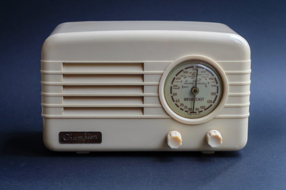
Champion Electric Corporation manufactured this 4 valve radio in the mid 1950s at their factory in Newhaven East Sussex. This one is serial number 44986. Encased in cream Bakelite the single waveband radio receives only MW (600 – 1500 kHz).
It’s a pretty basic design being TRF (tuned radio frequency) which is essentially like a crystal set with a variable frequency RF amplifier and an audio amplifier to drive the loud speaker. Better radios use a super-hetrodyne design which mixes the higher radio frequency down to an intermediate frequency (IF) amplifier which improves reception and allows automatic gain control.
A long length of wire is required for an aerial like that used on the Alba Midget see separate post. These are sometimes referred to as ‘throw out’ antennas and were replaced by internal ferrite aerials.
There’s no sign of cracks in the Bakelite case and the tuning dial has not yellowed or faded and looks original. This set is better suited as a display piece and was used as a prop. The mains cable has been removed.

Champion TRF 784 Dial
“Important on no account must the mains lead be shortened” appears on the rear as this set was fitted with a 300 ohm resistive cable to reduce the mains voltage down to run the valve heater circuit. Simply replacing the mains lead with a standard twin flex would damage the valves and components without the resistive feed.
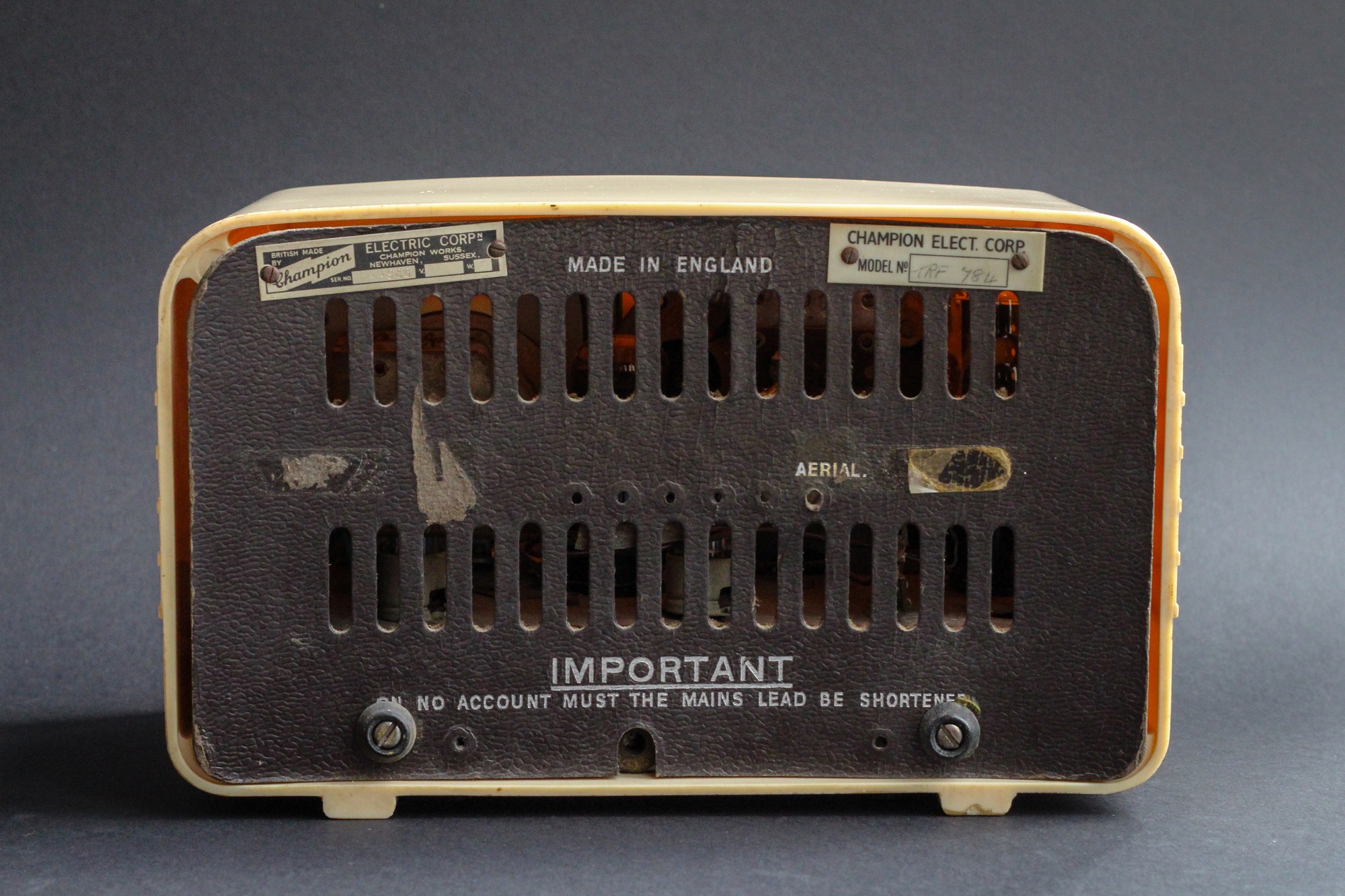
Champion TRF 784 Back
Like many radios of this period, no mains transformer was used and so the chassis is not isolated from 240v mains. It’s possible to replace the old mains lead by inserting a resistor inside the radio but typically a 30-40w dissipation is required which heats up the case and can cause discolouration and cracking. A later model 784 from Champion had the dropper inside the case instead of the resistance mains lead and you find many cases have cracked. Alternatively a capacitor could be used to avoid the heat dissipation but must be rated for continuous a.c.use and ideally fail open circuit to avoid damaging the valves if the capacitor fails. The UK Vintage Radio forum has many posts and a good guide on dropper calculations for anyone wishing to try such a repair.
Repairs or modifications to old valve radios should not be attempted unless you have experience due to the high voltages these sets have internally.
16/02/2021 at 3:08 pm
Hi, it’s great to see these lovely valve wireless sets on here especially this one as it’s the one my Mum had when we were all small and lived in the family home.
I became a radio & T.V. Engineer myself with a fascination of electronics and made it my career for 27 years after leaving school, however due to the economy and the fact no one had things repaired anymore it became a throw away society and no work for the service engineer, hence having to change career!
I’ve seen one of these Champion wireless sets on EBay and am very tempted to buy it but the seller is asking £60 for the postage which I think is a little over the top.
Do you know of anywhere I might be able to get one at all? I’d like to get one even if not working as I’d be able to repair it myself.
Kind Regards,
Jeff
16/02/2021 at 10:59 pm
Hi Jeff, thanks for your comments about the Champion. I still have the one I featured somewhere that I’ve not got around to repairing – another one of those projects. My father was the expert with valve sets, he too started a TV and radio service business and changed careers. It’s still useful to put old skills to use and keep the brain solving problems. Think I bought the Champion radio from eBay or a local charity shop. Postage should be no more that £10-15 for a small radio like the Champion. When we get back to normal times you could try searching car boot fairs as they do turn up if you get to them early. Good luck finding one or if anyone has one Jeff, post the details or DM me. Regards, Rick
16/02/2021 at 11:04 pm
Hi Jeff – there’s one with free postage on eBay now – https://www.ebay.co.uk/itm/Vintage-Champion-Radio-1950s-great-looking-piece-Antique-free-post/143947415442
04/11/2021 at 4:19 pm
Hi Jeff i have three Champion sets That i have repaired now my hobby. like you Jeff i had a career change in the 1970s i went into secuirity alarms for my last 20 years