
Do you have a Roberts Revival R250 or R550 radio with no sound? It’s a common problem with these radios most likely due to plugging in the wrong power adapter or replacing the battery with it switched on and accidentally reversing the connections. All you need is a voltmeter, soldering iron and some spare parts and it’s a fairly easy fix.
Warning – this gets technical but it’s really not difficult and you can have your radio working again in an hour or so.

After the obvious check that both speaker leads are connected, the first suspect is the volume control on the mini-circuit board. Connect a battery or 9v power source and measure the voltage either side of the the on/off switch on the volume control to make sure it’s not open circuit. If there’s 9v one side of the switch and 0v the other regardless if it’s switched on or not the volume control switch is broken and needs replacing. It’s very common fault as the spring contacts break inside the control and may not even click in the off position. More on that later – see Roberts R250 / R550 – Volume Control Fault.
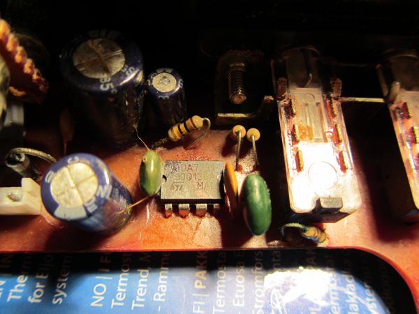
The second suspect is the 8-pin audio output chip that’s mounted close to the volume control on the main circuit board. Connect a battery or 9v power source and measure the voltage at pin 1of the 8-pin chip it should be about 9v. Pin 1 is marked on the printed circuit board. Try measuring voltage at pin 2, to the right of pin 1. If it reads 0v try disconnecting the loud speaker to see if the 470uF coupling capacitor is faulty. If it still shows 0v the chip has blown and must be replaced. If there’s around 4v on pin 2 the chip is probably working and if the voltage shows as 0v with speaker connected replace the 470uF capacitor as it will probably show as low resistance or short circuit. It’s just possible to replace the capacitor without taking out the main chassis.
To replace the audio chip you need to remove the PCB along with the top dial that’s held in place by two screws either side of the handle and the wooden blocks inside at each end. The blocks slide out after a small retaining screw is removed from the block nearest the battery and the telescopic aerial is unscrewed. The aerial is often loose or the 3mm screw missing. It’s a bit fiddly to slide out the end blocks and it’s possible to remove the main radio chassis with one block still in place if one refuses to move.
With the main chassis removed use a solder sucker or copper braid to remove as much solder as possible from the 8-pin chip. Then gently prise it out being careful not to break any copper tracks. Solder suckers work best as it’s faster and less heat required to remove the solder. With most solder removed applying heat from a soldering iron directly to a pin and gently moving the pin can help free each leg making it easier to push the whole chip out. Some pins may be folded over so need prising up with a fine flat blade screwdriver first.
Audio IC Chip
Sometimes you find the chip is glued in from glue they put around the larger components to stop them vibrating. It’s elastic glue and pulls away with a bit of force. With the chip free you should see the part number. There are two types: SIA2201X01 often just marked 2201 and the TDA7231 (used in the R550). If you can’t read the number look at the PCB – if pins 5 to 8 are all joined together it’s a TDA and it’s easier finding replacement parts. Roberts Radio spares are available but the older analogue parts are more difficult to find. If you can’t locate a 2201 part don’t throw the radio away! It’s still possible to repair it using a substitute LM386N-4 with a little tweak to pin 7 and 8. Just Google the recommended circuit configuration to see the difference. Pins 1-6 are the same and no change is necessary. The parts cost a few pounds so not an expensive repair if you have the tools and time.
Replace the chip taking care not to over heat each pin when soldering it in. I never bend the pins over when fitting just in case I want to repair it again as a second removal will often weaken the copper tracks and require additional fine wires to make good the broken tracks. Also make sure no adjacent pins have become accidentally joined by too much solder. Pins 1-4 should always be separate.
With the chip replaced connect the power and the radio should spring into life. If there’s still no sound and the 4v is now present at pin 2 then more investigation is needed but at least the audio chip should be functioning.
For other Roberts Radio Revival series faults try Roberts R250 – No MW / LW Hiss Fault
07/12/2014 at 7:07 pm
Followed your suggestions re Roberts Revival R550, got a TDA72321 for £2.19 and restored my daughter’s beloved radio to full working order. Bless you.
12/09/2016 at 9:37 am
i think the chip should be tda7231
12/09/2016 at 10:04 pm
Thanks Vince – you are right – I’ve updated the post to say it’s a TDA7231 as shown in the photo.
20/08/2023 at 2:08 pm
Hi Vince
I have a Roberts rd 50 dab radio thats been stored for approximately 15 years
Found mains adaptor and switched on all seems good! But no sound, but when I attach headphones I can hear something but very faint
Can you point me in the right direction please?
I have very little knowledge on this matter, but I am able to solder etc
Or should I write it off ?
Thanks
Dave Cook
21/08/2023 at 3:07 pm
As the radio been stored and there’s faint sound it may be tarnished contacts on the headphone socket. Squirt a little switch cleaner and insert the plug a few times to see if the sound improves. Best take apart to access the socket and clean with brush or fine card soaked in switch cleaner.
The RD 50 suffered from disintegrating faux leather case material – just flakes off – and it’s possible some debris has found its way inside.
Seems like others have experienced the same fault with faint audio – https://www.diynot.com/diy/threads/roberts-rd-50-dab-radio-sound-volume-issue.360434/ – and also suggested check the headphone socket.
Failing the socket, it could be volume control contacts – again try switch cleaner or leaky electrolytic capacitors around the audio chip – these can be replaced quite cheaply – note the polarity (+/-) before removal to ensure you replace the right way around.
Good luck and let us know how you get on, regards Rick
16/12/2016 at 6:24 pm
Please can you help?
We have an old school Roberts 550 which works but the volume has a poltergeist quality which either works on “full blast” and then goes very feint for no apparent reason…..also madly affected by anyone walking past. (eg you stand over it to tune it and then move away and the sound goes away.)
Any ideas ???
16/12/2016 at 10:37 pm
Most likely the volume control wiper has become tarnished and need cleaning. Does the volume change if you tap / move the volume control gently? You can get a switch cleaner from Maplin for a few pounds that has a fine flexible tube. Try to squirt some inside the volume control and rotate the volume fully back and forward several times. You’ll have to remove the back leather covered board (several small screws) to gain access.
If the switch cleaner does not work the volume control will need replacing – it’s 10K Ohm log potentiometer with a switch but can be fiddly to change and get to fit. Try google pot 10k ohm switch and you should find something suitable. Many are splined shaft pots that need filing a flat for the knob to fit.
Or it may just be Mr Harry Roberts’ ghost – does it get worse at full moon?
26/07/2017 at 6:16 pm
Hello there,
Thanks for this blog post its given me hope, I just plugged in my Roberts Revival RD-60 with the wrong adapter by mistake, it seems to have given up the ghost immediately. The red light comes on for a second, but then it cuts out 🙁
It was my Dads radio and I inherited it a couple of years ago so its really important to me.
I’m not an electronics person, but also can’t afford to fix it through Roberts Radio.
Would it be simple enough / the same on this model too?
If so, what might I need if I’m starting from scratch? Was hoping it might work with batteries in it but haven’t tried incase I damage it further.
Thanks for any help you can offer me
26/07/2017 at 7:16 pm
Hi Sophie
UPDATE: Different adapters for RD50 and RD60.
So the RD60 is a DAB/FM radio and not so easy to diagnose as there’s more electronic components inside. The correct adapter is 7.5v DC 800mA with positive polarity to the centre pin, PU34B. Was the wrong adapter you used positive centre pin? What voltage was it? Was it AC (squiggly line) or DC (straight line)? Useful to know what kind of damage it could cause,
The previous Roberts DAB model RD50 uses a different adapter is 7v DC 0.8A with negative polarity to the centre pin, PU11 Model RH41-0700800DB. So it’s easy to get the wrong one.
It’s worth trying it with batteries and switch it off quickly if it cuts out. The wrong adapter may have damaged the DC input before the battery supply so battery power may still work. I don’t have the RD-60 schematic circuit diagram to check.
If it still fails on batteries you may find a tatty one on eBay that works and swap the internal circuit boards to fix yours. Roberts did have a problem with the leatherette case material on the RD series that caused it to split and flake and so were cheap to buy second hand. Make sure it’s not an RD50 which has the different adapter.
17/03/2018 at 3:51 pm
Hi.. So can you tell me what that ‘tweak’ is on pins 7 and 8 if using a LM386N instead of the TDA? I’ve looked at the data sheet but I’m still confused.
Thanks in anticipation..
Dave
17/03/2018 at 5:28 pm
Dave – to replace the 2201 with an LM386:
1. Remove the resistor and capacitor connected to pin 7 so pin 7 is open circuit.
2. Remove the capacitor in series with 120R resistor (connected to pin 2) and replace with a wire link so pin 2 is grounded (0v)
3. Remove the capacitor connected to pin 8 so it’s open circuit.
Hope this helps.
Rick
20/03/2018 at 2:44 pm
Thanks Rick. Much appreciated!!
27/05/2018 at 2:26 pm
Hi I have acquired an old r250 revival but the aireiol has come out and doesn’t seem to screw back in, noticed screw missing from the bottom…. not at all clued up on these radios should the aireiol be attached inside to anything?
27/05/2018 at 2:54 pm
Yes, the telescopic aerial is attached with an M3 screw about 25mm long. As you’ve seen there’s a small hole at the bottom of the case for the screw to attach the aerial. There’s a wire with a tag that the screw fits through at the base of the aerial. The original screw has a countersunk head but a standard round head can be used instead. If your R250 has a back over you need to remove it (4-5 small screws) to help locate tag and aerial in place.
13/09/2018 at 7:21 pm
Hi Guys, great website to start with, very informative. I have a roberts radio r250 that has no sound, lights, nothing when connected to either power or radio. I did notice a very quiet crack when connecting the battery but nothing else. Do i follow the procedure for no sound above? im quite handy with soldering iron and avo meter so any advice would be gratefully appreciated. Thanks In advance Gary
14/09/2018 at 9:45 pm
There’s no light in the R250 dial. Try following the suggestions in the post. If it’s not the volume control switch and power’s getting to the audio chip then it’s most likely the chip needs replacing.
30/12/2018 at 12:56 pm
Hi, dad just got himself a Robert Play 10 radio. Lately, it would play for a while then volume goes off while other functions are quite okay. Please help.
30/12/2018 at 3:40 pm
Hi Sam – try plugging in headphones to hear if sounds comes back on. It could be bad contacts on the headphone socket that switch over the speakers when headphones are used. Inserting the jack plug a few times may clear it or switch cleaner could fix.
If no sound via headphones then it’s likely an intermittent fault with the audio amplifier. Check it’s not getting too hot when it stops or playing full volume?
01/05/2020 at 2:53 pm
Hi I’m replacing the audio chip in my rd250.
Does it matter which way the chip goes around.
I took a picture before I removed but it’s not helped.
Thanks
John.
02/05/2020 at 11:21 am
Yes, it does matter, you need to replace the chip the same way round.
There’s a notch at one end so ensure this notch is in the same position.
|=====|
) Chip |
|=====|
1
The notch is on the left hand side and in the picture. Pin 1 is below the notch and pin 1 above.
04/07/2020 at 2:10 pm
Hi
I’ve just bought a 2nd hand Roberts 550, MW & LW work fine however I get no reception from FM. The aerial comes out completely from the internal with the wire still screwed onto the base. Do you think this is the likely cause the aerial ?
Thanks Colin
04/07/2020 at 8:05 pm
Hi Colin, the loose aerial is unlikely unless you are in a low signal area. Our Roberts still tune in to several stations on FM without the aerial extended here in south of London. I’ve had a few R250 & R550s with the FM aerial broken – it’s a common fault. Roberts Radio spares did stock replacements a few years ago maybe worth trying them so see – https://www.robertsradiotechnical.co.uk/ExtPartsRequest.aspx
23/10/2020 at 3:44 am
Hi there, any idea for Roberts RD60 cannot power on (display light is on only) issue ?
25/10/2020 at 9:04 pm
Hi Justin, Roberts Revival digital series are not so forgiving when it comes to remote fault diagnosis. They either work or don’t so there’s not much of a clue and need more information. Is anything displayed on the LCD or just the back light?. Does it make a click sound through the speaker when switched on? Have you tried batteries and mains adaptor with same issue? Has the wrong power adapter been used?
If there’s nothing displayed is’s likely a logic board fault and probably needs replacing.
07/11/2020 at 6:31 pm
Hi,
Please could you help/advise me, I’ve got a much loved Roberts Revival Mini. It’s not working on mains power, only battery power so I went and tried another adaptor from my other Roberts (either RD50/60 I can’t remember which it is) and still no joy, only now I’ve realised it can damage them internally (and I’m gutted) if it was damaged by the wrong adaptor would it pack in all together or will it work off batteries? I’m going to order it another mains adaptor as I’ve tested the old adaptor and it’s given up the ghost. Are they easy to strip down and repair or is it easier to send it to Roberts for repair?
07/11/2020 at 8:13 pm
Hi Jac
Your revival Mini needs a PU34B ADAPTOR BLK(UK) 7.5V – 0.8A POSITIVE PIN. The RD50/60 has a PU11 which is 7v a negative pin so would not work and could damage the Mini. Try on batteries, if it’s still working the main radio board is not damaged so worth trying a new adaptor which are available from Roberts – https://www.robertsradiotechnical.co.uk/ExtPartsRequest.aspx?pid=Revival%20Mini&pn=PU34. If it does not work on batteries its best to send back to Roberts for repair. DAB radios are not very easy to repair without specialised equipment and the boards are not readily available as far as I know. You may find a working donor radio on eBay that’s cosmetically challenged as a low price and swap the board if you have time.
Unfortunately the adapter bodies are not repairable. The DC plug that connects to the Mini can be replaced if that’s where the fault lies. Sometimes the wire fractures at the plug. Cut it off, strip back the wires and test the voltage. A new plug will need soldered connections. Remember centre pin must be positive.
Hope you are lucky and it works on mains again.
Rick
10/11/2020 at 3:38 pm
Hi,
I have a Roberts rd-60 which I stupidly plugged into a 24v, 1250mA DC power supply. It made a quiet pop and I unplugged it. Would it be possible for a DIY repair? Interested in getting in to electronics anyway or is this way out of my league and better off sending it back to Roberts.
11/11/2020 at 7:50 am
If it was an analogue R250 I’d suggest attempting repair as it’s a good way to learn about Electronics. Analogue is simple – there’s an audio chip that drives the speaker and an IF and RF chip that receive the radio frequencies and provide the audio signal. Components are mounted on standard circuit boards that can be repaired – no surface mounted devices.
With DAB radios it’s a little more complicated but not impossible if you have the time and determination. The 24v DC voltage, rather than 7-11 v that the adapters provide, will have damaged components – the pop you heard is likely to be a hole in the audio chip, or blown electrolytic capacitor or a regulator blown that provides lower voltage for the digital logic chips. Digital chips run on 3-5v and need a voltage regulator.
Roberts don’t include over voltage protection in their sets for the obvious reason – if you mess up it costs you a new radio or a hefty repair. The cost of over voltage protection in consumer devices is minimal but most manufacturers don’t care and don’t include fuses anymore.
I don’t have the circuit diagrams / schematics / service manuals for the RD50/60 series to hand but you could search for them and see what’s involved. You may be lucky and the pop is an obvious component failure that you could try to replace if you can read the numbering on the popped component. It requires soldering and if its a surface mounted device needs some skill in removal as the printed circuit tracks are very fine and close together – it’s too easy to solder adjacent pins together and it won’t work. A solder sucker or solder wick aids removal.
The obvious component failure may have taken out other devices that are not so obvious. So it may not work by simply replacing a blown regulator for example as the regulator supplies the main logic board components these too could have fried. Fortunately many regulator devices are designed with protection built in and hopefully will not have damaged further devices down the line. Diagnosing faults from over voltage is not easy without test equipment such as oscilloscopes as the clock speed of the signals runs at high frequencies that simple multimeter can’t read.
So my advice would be to look and see if the damage is obvious and if not return for repair. Roberts are unlikely to repair to component level and will replace the whole board or boards affected if they have the spares. It may be cheaper than buying a new radio and you have the satisfaction of avoiding a throwaway.
Let us know how you get on.
18/01/2021 at 11:40 am
Hi,
Came across this and thought I would give it a go, instructions were easy to follow and the advice absolutely spot on. After 4 years of wishing I knew what was wrong with my radio; I followed the guidance, tested the chip, replaced it (with some generally tidy soldering given my inexperience) and now have a fully functioning radio.
I am a complete novice when it comes to electronics, soldering skills and ability to work with small fiddly components are not brilliant — if I can do this then anyone can.
Thank you so much for putting this information out there – it has saved me throwing a 20 year old present out and I am sure it will go on to provide the same number of years enjoyment again.
Neil
18/01/2021 at 9:49 pm
Hi Neil, thanks so much for the feedback – it makes it all worthwhile. Repair rather than throwaway is possible and good for the planet. And you have the satisfaction of the faulty radio jumping into life again. Yes soldering can be fiddly and you need a few tools but they can be used many times. You may find a friend’s radio needs similar treatment to hone your skills! Rick
23/01/2021 at 5:00 pm
Hi,
Just purchased a “dead” revival r250 in near mint condition & and I think one of the rarer colours…pastel lilac.
Removed the 1000uF16v elec cap which had clearly vented & the 470uF in front of it, as well as the TDA7231…which looked damaged. All are on order but a resistor in front of the “tone” control is blackened & the value is impossible to read. Do you know the value of this?
Best Regards
23/01/2021 at 11:27 pm
It’s 100Ω – looks like it feeds +v to the IF chip so maybe that will need replacing or one of the small buff ceramic caps has gone short circuit. Hope you get it working, the pastel colours were popular and if it’s the older R250 it won’t flake like the newer RD50/60 which disintegrate at a touch!
09/07/2021 at 2:01 pm
Bought second hand R250,works perfectly on battery. . Used Eco-Friendly 600mA adaptor adjusted to 6V , sound immediately ceases. Still works fine on battery. So what is wrong? (Total ignoramus )
09/07/2021 at 2:42 pm
Set adapter to 9V DC and make sure the adapter plug centre pin is negative (-ve). Hope that fixes it. Wrong polarity can damage some R250’s that don’t have reverse polarity protection.
12/08/2022 at 10:40 pm
My Roberts R550 radio was exposed to the sun and became
very hot and the sound became very distorted.
On cooling down the distortion disappeared and the sound is back to normal. Is this a common fault.
13/08/2022 at 8:35 pm
As you’ve found it’s best not expose electronic devices to high temperatures. Most silicon based semiconductors will operate up to 85℃. I measured temperature of 60℃ on the lawn in full sun yesterday although darker objects will absorb more heat. Older transistor radios, like the original Roberts R500, popular in the sixties used germanium semiconductors and these devices suffer from thermal runaway so could only operate at much lower temperatures – one reason silicon fabrication replaced germanium. So your silicon based R550 should have coped with the heat – the audio chip may be designed to shut down at high temperatures to prevent destruction and that’s why it sounded distorted and recovered on cooling. So guess you could say it’s expected rather than a common fault – in car audio works over a higher temperature range that household appliances without issue.
13/08/2022 at 10:01 pm
Thanks Rick l will ensure that is not exposed to extreme temperatures again.
I purchased this radio some years ago only having to replace the on/off volume potentiometer.
14/08/2022 at 7:14 am
We made the mistake of leaving a maroon R550 I repaired in the greenhouse and noticed it didn’t like the full sun – the case started to fade. Also seen the RD50 digital version of the R250 being used in glasshouses with cases peeling – the covering Roberts used on these really didn’t wear well. The tatty ones had an aftermarket life though as they were being recovered in trendy fabrics so as I say – don’t throw it away!
15/08/2022 at 7:18 am
Thanks Rick, l will keep it in a cool place in future.
07/10/2022 at 9:06 pm
Hi I have come across a Revival R500 in burgundy in pristine condition. Works okay but the aerial is damaged and needs replacing as it can tune into any stations. Can someone point me in the direction of somewhere that can supply a replacement aerial ?
18/10/2022 at 12:58 pm
Have you tried Roberts Radio spares? https://www.robertsradiotechnical.co.uk/ExtPartsRequest.aspx
They may be able to supply a replacement.
14/11/2022 at 10:12 pm
Hello, I have a Roberts mini dab radio. On switching on the display works perfectly will tune to stations but there is no sound. There is no sound from the headphone jack either. Any ideas?
15/11/2022 at 11:12 pm
Not sure which model you have but there are some things you can try to identify what could be wrong. Most likely an audio chip failure that can result from incorrect power adapter. Some Roberts DAB sets also have an FM option so check if there’s any sound from FM. Also some have an Aux input so check this as well. If there’s no sound and no faint buzzing from the speaker with volume at max the audio output chip will need replacing. If FM works it could be the mode switch. Also check on battery power and via an adapter as I did have a RD-50 that was temperamental on DAB that worked only on battery.
16/11/2022 at 12:11 am
Hi Rick, I tried the aux in and no joy.No sound in either fm or dab. No sound. I assume it may well be the chip needs replacing. The radio is from the Revival mini range. It seems both pcb boards are difficult to access. They seem to be almost glued in. I presume the amplifier section is near the battery compartment. Roberts repair service want 65 pounds to repair. If i can gain access I will swap over the op amp myself.
16/11/2022 at 8:53 am
Access and repair to component level for the later Roberts series is very difficult. Probably explains the cost as they replace the whole pcb. May just be held by push click fixings like remotes and needs small spudger pry tool to release. I haven’t seen the one you have – worth trying youtube search as someone may have tried. Good luck!
30/01/2024 at 2:41 pm
Hi Rick,
I have inherited a Robert’s revival R250 253570 with no lead. Works fine on battery but I’d like to run it on mains if possible. It says 9v PIN -ve on the portal. I’m seeing adapters for sale with reviews saying they broke the radio, so asking you which is the correct one please? Thank you!
30/01/2024 at 4:12 pm
Hello Dolly, you will need a PU609 adapter that has a negative centre socket. If you want to listen on AM (MW/LW) avoid the longer thinner switching adapters and look for a box shape one which uses a transformer. The cheaper adapters produce radio interference.
26/03/2025 at 7:33 am
Hello mr. Rick from Ukraine!i am restoring Robert Revial 250 and everything is already fine, but I want to connect Bluetooth module so when you click on MW(its not working in Ukraine) then turned on Bluetooth and play music from iphone(its a pink one, for lady). I cant find R250 circuit diagram….and cant do this…audiochip is tda 7231..can you help me with that?..
26/03/2025 at 8:51 am
Hi Salko, here’s a r250 circuit https://storycase.co.uk/radio/wp-content/uploads/2012/11/Roberts-R250.pdf I have added a Bluetooth module to an R250 so here are some tips. It’s best to power the module directly from a separate battery to reduce interference (buzzing noise). You can add a 5v regulator and power from the R250 9v supply but it needs a thick ground (0v) wire as the 0v is also the signal ground return. I rewired the Tone switch to power the module only when pressed and to switch over the audio input from radio to Bluetooth. This avoids running battery down when using on FM/AM only and no need for Bluetooth. Also stops any interference from the module when receiving radio programmes. Good luck, it’s worth converting makes a useful radio.
26/03/2025 at 3:58 pm
Mr. Rick, can you help me to understand how to discharge MW and connect power to Bluetooth module(its with galvanic anti nice circuit 5-24 v, and where should I connect audio from Bluetooth and disconect forever for MW?I spent hole day but can not find where is C19 condenser and where should i brake all MW. Can you draw it on circuit diagram for me?(Sorry i am really new to thos Sphere..
26/03/2025 at 8:59 pm
There’s no easy way to disconnect MW or LW to connect BT module. You need to rewire the audio. The R250 has one audio output from IC2 (BA-4236L) via the capacitor. It’s best to cut the circuit board track and solder a wire from the negative side of the capacitor to the top contact on tone switch. One pair of changeover contacts are not used on this switch. Then wire the centre contact to the other side of the track you cut – this feeds the volume control. Then wire the left or right channel from the BT module to the lower switch contact. So when you press the tone switch done it connects the BT audio and disconnects the radio audio. With the tone switch up the radio will work on all wavebands even if you can’t receive any on MW! It’s more difficult to disconnect the RF coils from the MW switch and rewire as it’s switching radio frequencies rather than audio – more to go wrong! I’ll try and add a sketch showing the connections. Hope this helps.
26/03/2025 at 9:04 pm
Thank you for response!!!if it not easy to make it with MW lets do it with TONE knob!but i want to save high frequency mode!so we can turn of TONE change to low frequency and use this knob to Bluetooth!
26/03/2025 at 9:27 pm
Here’s the modification sketch. Have added two resistors to combine both L & R BT channels rather than just using one channel. Any value between 100 to 2200 ohms will work. Best avoid connecting left and right channels together directly though. https://storycase.co.uk/radio/wp-content/uploads/2025/03/20250326_211709-scaled.jpg
26/03/2025 at 10:04 pm
My dear friend, you saved my nerves and the project!! How can I thank you, sir?