
So a rather old Paradigm PDR10 sub woofer I bought over ten years ago from Richer Sounds Sevenoaks had developed some faults and needed servicing. It would have been too easy to just throw it out but after a few hours effort it’s working again sounding even better that before.
Warning: Never operate you sub-woofer with the amplifier removed – there are exposed mains voltage connectors inside and the amplifier has a heavy transformer that can topple over!
You may too have one of these subs that needs similar treatment so here’s what to expect and what may need doing.
First the rattle, most obvious on movies such as Star Wars Revenge of the Sith on the opening sequence. The whole front baffle vibrates and rattles as if it’s going to fall off. There’s no obvious fixings from the front grille. A quick Google finds several questions asking how to remove the front grille followed by pictures of broken baffle and the answers – it’s not designed to be removed!
Disconnect all cables, place the sub on its front and remove the black chipboard screws holding the power amplifier in place. Lift the black metal plate holding the transformer and power amplifier carefully out removing the red and black speaker cables and the plug connecting the front power indicator. Remove the white wadding that surrounds the speaker – it simply lifts out as it’s not glued in place – more on that later.
Next remote the speaker held in place with longer black chipboard screws. My speaker showed no signs of foam rot on the cone surround that could have caused the rattle – see my other post if your sub has a damaged surround Paradigm PDR10 Foam Rot Replacement Sub Woofer Fix. So I put the speaker out of the way of metal tools and feet and looked more closely at the cabinet.
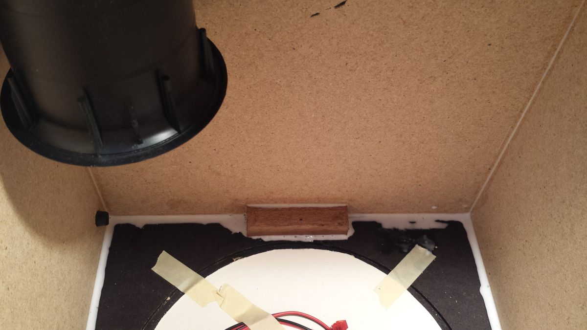
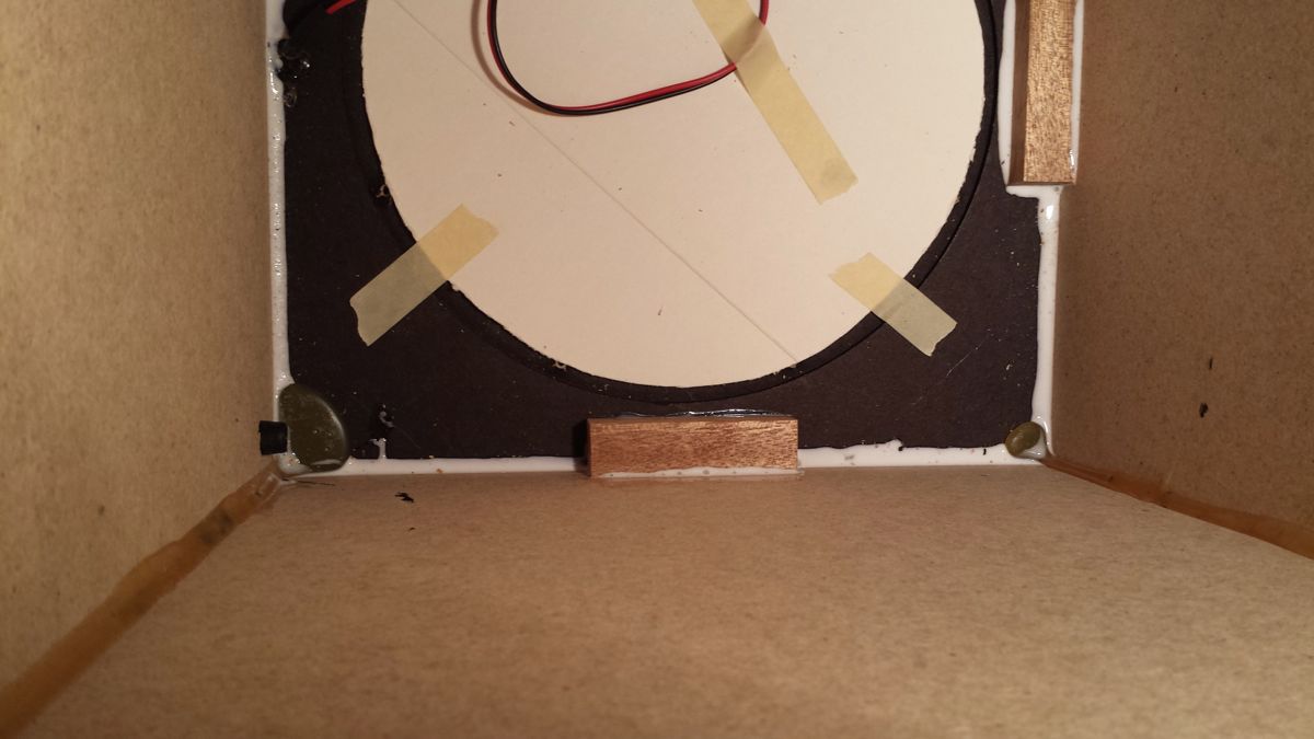
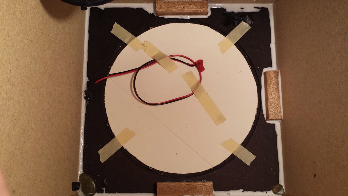
Inside my PDR10 there was no glue seams along the front baffle board or two of the cabinet sides – see photos. There was however glue on the other two cabinet sides. It looked a Friday afternoon botched assembly where they forgot to apply all the glue but PDR10s may all be like this. I made up three bracing blocks from some pieces of hardwood I had in the workshop. I made a cardboard disk to put in place of the speaker to avoid getting glue on the grille material. Then I found the PVA wood glue – a fairly runny consistency – and applied liberally all around the inside edges in the hope it would seep between the front baffle and sides. You can see the result.
-

- Paradigm PDR10 – Glue missing from edges
-
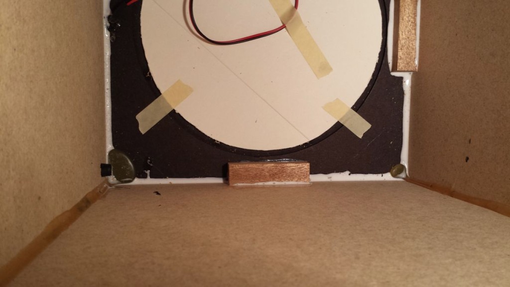
- Paradigm PDR10 with blocks added
-
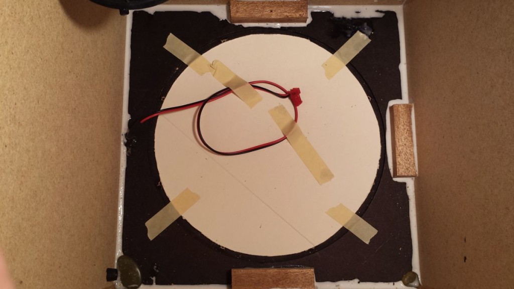
- Paradigm PDR10 temporary cardboard in place
Although fairly warm at 22 C the glue still looked white after an hour. The inside had little air movement so I added a small PC fan blowing down into the port to help dry the PVA. Next day the glue has turned clear and set. Hopefully the baffle would no longer move.

Paradigm PDR10 showing glue dry inside cabinet
Next the hum and the circuit board. First problem I noticed that two resistors R81 (2K7Ω) and R82 (5K1Ω) had fried. The PCB was scorched around the resistors and the solder joints looked suspect. The resistors are connected in series to make a 7.6KΩ dropper from the 240v mains for I guess the standby power supply so they are always hot if the sub is left plugged in. Reminded me of the old valve radios with hot running resistors although these were only hot when the radio is on!

Paradigm PDR10 Burnt Resistors and PCB
To desolder the resistors it’s easiest to remove the metal side panel. This is held in place by two screws from the back panel and a square headed security screw from the side panel that holds the heatsink in place. The square headed security screw needs a special driver bit. A small flat bladed screw driver may work across diagonal if you have one that fits.
I found an 8KΩ wire wound resistor to replace the two smaller wattage resistors that had cooked. This avoided using two of the solder connections that had suffered overheating. A quick calc shows this resistor could dissipate over 6 watts if it’s dropping 220v so it’s no surprise it cooks the PCB if it’s left on all the time. Will check the voltage drop next time I open the sub. It’s not a good design and would hope newer versions of the PDR10 use a small transformer or non resistive supply instead for standby power.

Paradigm PDR10 Replacement Wirewound Resistor
Hum is most likely due to faulty smoothing caps and I noticed one of the two large black electrolytics showed a domed top compared to the other. The suspect cap was removed with help of a solder sucker or you could try copper braid. Helps to heat one side and gently rock the cap to pull each pin gently as you apply heat from soldering iron. Have to be careful not to press too hard and break the PCB tracks. The faulty capacitor is marked 5600µF at 50v 85C. It’s a 30mm diameter electrolytic and I only had a 4700µF 100v one that fitted temporarily.
Reassembly of the metal plate just needed the addition of a small stick on rubber disk on the end of the PCB mount where the top had disintegrated due to the heat from the resistors. This I hoped would avoid more rattles as I did not have a replacement plastic PCB mount.
Before replacing the power amplifier I turned attention to the wadding that looked added as an after thought. I found some more sound deadening foam and cut it to fit top and bottom and around the port tube. Gluing in place with Copydex. The remaining wadding was cut to fit either side nearest the front baffle and again glued to the inner cabinet. I left the area above the power amplifier PCB to avoid heat from the resistor getting near any wadding.
With the glue dry and components replaced the speaker and power amplifier can be assembled – the PCB shows the red and black speaker connections and the indicator lead clicks into place. I put a couple of fixings in place and applied power for a few minutes to see how hot the new resistor got. It seems okay with no discolouring so I reassembled and fired it up. Perfect, no rattle or hum just nice solid bass shake. So I’ll order two replacement caps when I get time.
Update – Replaced both reservoir caps with10,000µF 63v electrolytic and sounding excellent.
26/01/2016 at 2:13 pm
Hey Rick, nice write up here.. I have a PDR12 (v1) with the same exact issue.. I replaced the surround foam and the speaker is operating like new.. The hum remains.
Where can I get the specified resistor that you’re using? I’m not assuming that you’d know the answer to this – but do you think the components on your board are identical to the components on a 12″ model’s board?
Thanks for any replies.. It was a miracle to find anything about this amplifier backplate.. Especially in write up form!
26/01/2016 at 2:46 pm
Thanks LJ, glad it helped. The wire wound resistor should be available try eBay look for 5 Watt wirewound – 8K2 may be easier to find or put two in series that add up to 7K5. Note sure if it’s same on the PDR12 but guess they used the same circuit. These resistors on the PDR10 drop the mains voltage so I’d try measuring your resistor’s value with an ohm / multi meter to check the value. Obviously not while plugged in and best remove resistors from board first.
17/09/2016 at 11:16 pm
Hello Rick. I was looking for a circuit diagram for a PDR-10 sub when I found your post. I have a fried R34 resistor on the board and need to know the value of it. Do you have a schematics that you are willing to share or a picture of the full board so I could see the color code? Thanks.
18/11/2017 at 6:35 pm
Hi Rick,
Excelllant write up, I have found myself with the same issue! Could you please tell me the exact value of the wire wound resistor you used?
Reformed the speaker, just need to do the resistors,
Thx,
Rob.
18/11/2017 at 7:32 pm
I used a 7.5K ohm.
31/05/2018 at 8:39 am
Hi, great article……I’ve had a pdr10 sub in my system for around 10yrs, but lately it started rattling etc, I took the back off and carefully felt the cone and found the foam surround has split in couple places……is it possible to repair or will I need a replacement speaker?….I assume a good quality 10inch sub driver rated at 100watts would be ok?…..Regards….Kev.
31/05/2018 at 8:41 pm
Thanks, you can find 10″ replacement foam surrounds for around £6 mostly imported from China. I’ve never tried them though. Have bought hifi quality replacement surrounds for 3″ B&O woofers from Dutch supplier that seemed good quality. You can use standard PVA glue – takes 12-24h to dry out so allows time to centre ring accurately. I’ve kept my old woofer to try and re-foam when I get time. As mentioned in the other post https://storycase.co.uk/radio/restoration/paradigm-pdr10-foam-rot-replacement-sub-woofer-fix/ I found a good sub driver for £30 that was easier fix.
24/01/2020 at 3:04 pm
Late comer here but this report is just what I needed.
I had the foam surround issue which I replaced using a rubber surround that I purchased from ebay.
The altered the dynamics and the cone was to flimsy for it so I stiffened the cone using a paint on mix of PVA glue slightly watered down. Then applied a few more coats of straight PVA. The cone is now practically solid and after improving the deadening in the enclosure, the performance is so tight now. Much tighter than previously. The problem I have now come to is the hum. I noticed the face plate of the amp was somehow electrically charged so made a simple earth and connected ot to the negative terminal in the rear of the kettle socket.
The hum is now next to inaudible.
However, if it returns I will be upgrading the capacitors as a matter of course.
24/01/2020 at 5:18 pm
Thanks for your interesting report Paul. Like the idea of PVA to stiffen the cone. The rubber surround I bought from eBay was quite flexible and I did not notice a problem with the cone although I’ve not replaced the driver in the enclosure yet – just bench test, so may find the same issue.
WARNING Re earthing – Never connect the face plate to mains terminals on rear of kettle socket! It could allow dangerous mains voltage to be present if the negative and positive terminals (live and neutral) are reversed for any reason. It will also trip an RCB if the mains neutral is earthed e.g. via an input connector. I’d look for the reason your face plate is charged. What sort of voltage is it sitting at? Try an ohms test between the plate and the outer phono input. You may find using a 0.1uF capacitor between plate and the audio input ground stops the hum.
The kettle socket earth is not connected to chassis to prevent earth loops if the phono connector is used and the source amplifier ground is earthed. Earth loops are the plague of single ended amplification across multiple sources and need one single earth point to avoid. Balanced inputs stops the problem but cost more so not often used on domestic kit.
26/01/2020 at 10:19 pm
The hum is probably be due to the main reservoir electrolytics (the two 5600uF/ 50v capacitors) drying up due to age. On my PDR10 one of the capacitor’s top look domed rather than flat, an indication it had overheated. Check the rectifier diodes as well, you can see two of the four diodes next to one of the caps in the post. Low capacitance causes mains frequency ripple on the power lines hence the hum.
16/12/2020 at 7:48 am
Hi Rick
Really really late comer.
Any volume placed on my 12 year old PDR 10 (seven oaks purchase too) creates massive distortion.
Going to have a go at dismantling and replacing the speaker with the Skytec you mention in a subsequent post subject to a degraded surround.
If the surround looks good and it’s electronic in nature, then thats out of my comfort zone.
Interesting read btw. Thanks
Neil
16/12/2020 at 1:16 pm
Thanks for the comment Neil. Worth checking the speaker, I have the original I re-foamed and never fitted so you are welcome to have if you can’t find a replacement. I had to replace the main smoothing capacitors in my PDR 10 so when you dismantle check the top of both caps to see if they are domed rather than flat. Component failure, especially the electrolytic capacitors could be the cause of the distortion, but most likely speaker surround rot so check that first.
19/12/2020 at 6:46 pm
Will do Rick. Thanks for the advice. Replacement surround and copydex has arrived. Removed gasket. Came apart but copydex has put it back together. I’ve ordered a replacement gasket that may fit. Residual glue is off. Will check electrical components when new gasket turns up. If all fails may be in contact to negotiate purchasing your speaker.
Cheers
Neil
20/12/2020 at 9:30 am
The cardboard gasket split / delaminated when I replaced the surround on my PDR 10. I used PVA to glue the gasket back together and fix in place. It gets compressed when mounted so should be fine. Hope it all works, nothing quite like fixing it yourself!
31/05/2022 at 11:23 am
Very late to the party here; but do you have any info on the size of the required capacitors for replacement? I have looked at available options on RS and there seems to be many, I assume differing in diameter and pin position. Do you have a link to what you purchased at all?
31/05/2022 at 8:32 pm
Found the old Paradigm 5600uF 50v which is 30mm diameter 40cm tall. Don’t recall the replacement I used but there are several 10000uF 63v that are 30 x 50mm which look similar. There are also low profile – larger diameter – versions available but at 36mm diameter may be a tight fit so I’d stick to the taller 30mm diameter options such as RS’s Cornell-Dubilier SLPX103M063E9P3.
08/05/2024 at 3:38 pm
Hi Rick,
Not sure if this thread is still active or not, but worth a shot! I am just wondering if you have any advice for the PDR 10 that seems to be lacking Volume. The sub use to work great but I have noticed now in order to hear the woofer like I once use to, the volume has to be cranked full. Also just an FYI my ears still work, so that’s not is the problem.
I’ve also checked all my amplifiers settings and nothing has changed with respect to the subs levels. I also see my R81and R82 look cooked as well similar to your photo above, so not sure if these would impact the output of the speaker.
Additionally, if you have a schematic you can share, I would love to trace through my board and see if any other resistors/capacitors are shot.
Cheers,
CA
09/05/2024 at 8:14 am
The cooked resistors won’t affect bass level as they just provide low power for the auto standby circuit. I’d replace the two reservoir caps (5600µF) as suggested in the post. You can find 10000µF 63v low ESR caps that should help. Worth a try first.
09/05/2024 at 6:28 pm
Thanks Rick, I will give it a shot. Appreciate your response.
09/05/2024 at 8:41 pm
Also worth checking if the foam surround has perished which may explain low output volume – see my other post Paradigm PDR10 Foam Rot Replacement Sub Woofer Fix