
Does your Beomaster 3000 / 3000-2 blow its fuses? Or sound distorted?
There are several common faults that are fairly simple to fix with a little patience.
Warning – this gets technical and requires some knowledge of electronics and soldering but it’s really not difficult and you can have your Beomaster working again in a couple of hours or so. As with any mains powered device always follow manufacturers instructions and Never operate your Beomaster with the top open and connected to mains power. I cannot be held responsible for any damage or injury you may sustain.
Bang and Olufsen’s Beomaster 3000 tuner amplifier is an impressive design but requires large high value electrolytic capacitors and uses fragile preset potentiometers that fail with drastic results.

Blown fuses – If the mains fuses blow the most likely suspects are the three large tubular capacitors. An ohms check can indicate if this is the case – a steady resistance of a few ohms indicates a failed capacitor, although they can breakdown only when voltage is applied and pass the ohms test. It’s best to disconnect a wire from each to isolate the capacitor and measure its resistance without the rest of the circuit connected. Note the polarity (+/-) on each wire to make sure each electrolytic is reconnected correctly. Damage will result if these electrolytic’s polarity is reversed.
The slightly larger capacitor is a 5000µF / 70v main smoothing reservoir. It should be replaced with at least 4700µF. Modern electrolytics are much smaller so it’s possible to choose a higher value and higher voltage rating and it still fit. Make sure the capacitors can cope with the ripple current so they don’t overheat. I prefer increasing the value to at least 6800µF or 10000µF / 100v rating and 85ºC working temperature with screw terminals. If you want to retain authenticity keep the original value.
The right and left amplifiers use a 3000µF coupling / blocking capacitor located either side of the main reservoir. These are rated at a lower 35/40v as the output stage sits at around 30v – half the 60v dc supply. But the audio signal will swing to near 60v when driven hard so I suggest replacing both with 4700µF rated at least 63v. Higher voltage components are physically larger so will be closer in size to the originals and fit. Replace both even if just one has failed. See end of post for examples of leakage.
With all three capacitors replaced with luck it should switch on without blowing the fuse.
If not there are few few other PCB mounted components such as the skeleton presets and smaller electrolytic capacitors that will need investigating and will be the subject of another post. In the meantime if you are tempted to replace the smaller electrolytics make sure you observe the polarity of each before removal to ensure it’s replaced the right way around. I suggest marking the negative with a black dot from a Sharpie marker pen and take a photo before you start!

BM3000-2 Main Amplifier PCB

BM3000-2 Left Channel Schematic

BM3000-2 Right Channel Schematic

BM3000-2 Amplifier Capacitor Replacements

BM3000-2 Left Channel Amplifier Capacitor Replacements
Check out other comment on the Beomaster 3000-2 here BANG & OLUFSEN BEOMASTER 3000-2
Electrolytic capacitors
Here are some examples of the original electrolytic capacitors that have been replaced showing evidence of leakage. Click to zoom.
-

- 3000uF35v details
-

- 3000uF 35v showing blistered vent
-

- 3000uF 70v details
-

- 3000uF 70v staining age
-

- 3000uF 70v electrolyte leakage
-

- 5000uF 70v details
-

- 5000uF 70v electrolyte leakage
-
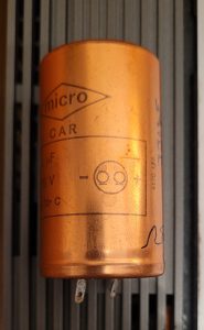
- Connections – note tags at bottom left is -ve
01/02/2015 at 12:02 am
Thanks for the informative article. I have a 3000-2 that seems to be working okay, apart from: a) the Tape input seems to have a dirty or oxidised switch because it only plays through the left channel. When I move the Tape selector switch up and down, the music comes through both channels. I’m hoping to fix this with DeOxit D5.
The unit also hums after being switched on for 10 minutes or so, and the hum gets louder. Do you think this would be fixed by replacing the capacitors?
Can you suggest a suitable brand and model of capacitor? If I go along with your suggestion of higher rated capacitors, will this change the quality of the sound?
Thanks!
01/02/2015 at 10:30 pm
Yes the intermittent input selector switch often needs plenty of cleaner – helps to let it soak for a while and cycle through all switch combinations as many times as you can.
Depends if the hum is mechanical – the transformer can vibrate and the whole unit hums especially when placed on a shelf that acts like a sound board. This may get worse after it heats up – the transformer is potted in a silicon glue inside a steel box that rusts – think potting compound ages hard. Not much you can do about mechanical hum and a heart transplant from another Beomaster is the only option.
An increased hum after switch on when audible through the speakers could be the main smoothing cap. If both channels hum I’d start by replacing the centre 5000uF. Do the output transistors on the rear heatsink get warm to touch and similar on both left and right channels? If one channel is hot it could point to a leaky coupling cap with dc current flowing through the speakers. I’d change both 3000uF coupling caps even if only one channel is affected though.
I’ve used Nippon Chemicon KMH range rated at105 degC and work well. Panasonic are also good. The snap-in range are popular and can be soldered. Larger values 6,800 – 10,000 improves bass at higher volume.
Good luck – it’s worth the effort.
07/02/2015 at 8:57 am
Thanks for your detailed reply!
The switch problem was solved with deoxit and the unit now works like normal.
The hum is definitely from the unit and not the speakers. It’s inaudible at first but after 20 mins it’s annoying!
All caps etc look healthy inside (at least to my inexperienced eye).
If the transformer needs replacing, do you know if the process is easy? Risky? Worth doing?
Many thanks again
09/02/2015 at 10:15 am
I found no easy option to cure the transformer hum, see this post – http://forum.beoworld.org/forums/t/2971.aspx. You could try thin rubber strips between the transformer case and chassis with mounting grommets – this did help me reduce vibration although not eliminate it. The transformer acts like a buzzer in the steel box so dampening these will help.
For authenticity, replacing the whole box from another faulty Beomaster with a good transformer is best option. One out of three units I had one hummed though and ended up selling the BM as ‘with hum’.
You could replace it with an 0-22, 0-22v toroidal transformer for about £25 – may not have the same primary voltage taps as the original but should guarantee quite operation. Need to be careful if mounting back in the steel box that the centre bolt of the toroid does not touch the case both sides causing a shorted turn! To reuse the box you’ll need to cut around and prise out the original transformer – may find the loose lamination. Always a risk with mains voltages and since the unit is not earthed need to be very careful all mains wiring is double insulated. Worth it though to get a silence unless you buy a good pair of headphones 🙂
18/06/2015 at 1:28 pm
Hi, first of all thanks for this helpful post.
My receiver also had a audible hum at higher volumes, but suddenly stopped working, it switches on but now gives a very loud signal of 50 hz, regardless of any inputs (even with no input it still gives this sound).
demonstration: https://www.youtube.com/watch?v=kQNXIt9zMQE
Could this be the caps as well, or is this another problem. The caps themselves don’t look bad (no leakage).
18/06/2015 at 6:24 pm
Hi Gerbert
Thanks for your comment.
If the hum is from both speakers – difficult to tell from the video – it’s most likely the main reservoir cap (5000uF) the larger of the three big caps. It feeds dc supply to both L&R output amplifiers.
Or it could be another decoupling cap that’s gone open circuit. You said it’s been humming for a while so probably the main cap. They often fail short circuit and blow the fuse but can slowly vent the electrolyte go dry and open circuit so there’s no smoothing of the rectified ac which causes the loud hum.
There are many other possible faults such as a blown output transistor pulling the main supply low. But as it’s not blowing fuses it’s less likely I guess.
Would not keep it switched on too long with this fault as it may damage other components. I’d try replacing the main reservoir cap at first.
Good luck!
Rick
18/02/2017 at 3:00 pm
Any luck solving this? Was it the main reservoir cap? I just saved an old Beomaster from the dump, but it has the same symptom — when switched on, I immediately hear just a very loud AC power signal through all speakers.
20/10/2015 at 4:08 pm
Hiya I have an bang & olufsen beomaster all lights up can tune until stero light comes on got hold of a speaker but still no sound got a 2 pin din plug only added on speaker to it though speaker does work any ideas many thanks for your time
20/10/2015 at 9:35 pm
Try some headphones – needs 1/4 inch jack plug – to check if the amps are working. If so check the speaker switches 1 & 2 as the contacts often need switch cleaner. Try the switches up and down several times and the speaker on both L & R channels – the din sockets often tarnish black and need switch cleaner. If still no sound suspect the power amps are faulty.
21/08/2017 at 10:02 pm
Hi, Have a BM3000 with a 50Hz hum in only one channel, with headphones. So its not the output stage.
Left channel seen from above the preamp. All three main caps changed. Still there…
When you say decoupling caps, do you mean the small metalfilm striped ones? There is one per channel right next to those main caps, by those point to point soldered resistors.
Or any other problem area that would cause just the one channel to have the hum through headphones?
22/08/2017 at 10:33 pm
Hi Marcus, on the BM3000-2 the headphones are driven from the output stage via a 180 ohm resistor. So I suspect the smaller electrolytic capacitors need changing on the main amplifier circuit board. There are three that smooth the 60v supply. C546 50uf 50v (replace with 47uF 63v), C533 100uF 35v and C505 10uF 70v. If the left channel hums with the volume set to minimum then try changing C546 and C533 first. All the orange / grey plastic cylinder capacitors would be worth changing to avoid similar problems on the other channel. I’ll add a picture showing these caps to the post. Hope this will reduce the hum.
23/08/2017 at 8:44 pm
Hi Rick, many thanks for your tips. I have changed them all, no difference.. well the bas is very nice when I crank the volume up, hides the hum aswell :=) but volume to zero (or any level) on the tape or phono inputs with nothing playing and its there in the same channel…
Realy no matter what button i press (hi/low or mono L/R etc).. no difference.
I don’t get it.
thanks
24/08/2017 at 8:52 pm
So seems you have an interesting fault! I’ve uploaded some pics of the amplifier circuit to suggest some ideas to try. So if there’s hum from left channel only when volume at minimum it’s either coming from ripple on the main 60v DC supply (more likely 100Hz as it’s full wave rectifier) or the volume control wiper is not returned to ground (0v DC) or there’s an earth return high resistance somewhere. Is the hum definitely 50Hz?
If you look at the left channel amplifier circuit there are two smoothing caps C546, C533 after the volume control that you’ve changed. There’s also C553 100uF 35v that’s a bootstrap cap that could affect the gain at low frequencies if it’s leaky so could try replacing if you have not changed already. Also try switch cleaner on the volume, base and treble sliders as the wiper can tarnish and go high resistance on just one channel. The bass / treble are after the volume control – do any crackle when you move them? Does the hum change if you set volume to minimum and move bass / treble slider?
Did you break or not reconnect any of the earth return wires when you changed the main caps? Few things to try.
28/08/2017 at 5:57 pm
Hello Rick, all electrolytic caps changed. to no avail. All slider pots thoroughly cleaned and lubed, no change. Every earthreturned wire resoldered, no change :=(
I do think your right, its not 50z but 100hz. But the rectifier (behind the transformer) supplies both channels, so any issues here would make both channels humm right?
The hum doesn’t change with volume or adjustment of any of the other sliders (not even balance), its there on all inputs, both phono, tape and FM, no matter if I play with the mono switches. always left channel and always there.
Even thought it was my headphones, so tried two others, but it is there.
Even changed some of the metalfilms..but nada… could it be something being fed through the preamp? But then FM is not involved in the preamp, its only the otehr inputs.. so hardly that, right?
ANY creative ideas welcome :=)
09/11/2018 at 7:52 am
Great post Rick, lots of new ideas to get mine fixed.
The problem i’ve encountered is a distorted chanel sound.
Right is doing fine, left sounds scrambled ( crackling ).
Sliders are all clean. Switches too.
According to your post here i may have to check the main caps am i right?
Thanks in advance.
09/11/2018 at 9:07 am
Hi Steve – as only one channel is distorted I’d check the mid point voltage of both power amps to see if they are the same. Measure the voltage across each 3000uF capacitor (the two slightly smaller ones in group of three). It should be about half the supply voltage so around 35v with speaker connected. If they both are the same try changing the capacitor on the left channel.
23/01/2020 at 10:30 pm
Please change both the rectifiers (PSU and tuner) at sight. New capacitors of any size
will blow the rectifier in time due to increased surge current due to todays much lower
impedances (ESR). The tuner rectifier is an accident waiting to happen, bad from start.
Otherwise, dried out capacitors is the main problem, contact oil on trimpots.
02/06/2020 at 6:47 pm
Hi Rick. I have just noticed that my Beomaster 3000-2 has no treble gain in the left channel at all (Checked by switching to mono). Is this an easy fix? I am going to take it apart anyway to clean the switches with Servicol spray cleaner and will check fir disconnected wires off the sliding pot…thanks Dave
02/06/2020 at 8:44 pm
Should not be difficult to fix – start with spray on the treble slider, the left channel contact’s probably tarnished and open circuit. You could check with an ohmmeter compare with right channel as you move the slider. If it’s not the slider itself, check treble is the same from all input sources to narrow down to preamp or power amp and trace back. I found the preset potentiometers (pots) also go open circuit and in some cases fall apart if adjusted but these usually affect gain at all frequencies. Good luck and let us know how you get on. Rick
04/06/2020 at 4:48 pm
Thanks Rick, I will let you know how I get on. Cheers
04/06/2020 at 4:50 pm
Thanks Rick will let you know! 🙂
27/06/2020 at 6:20 pm
Hi Rick
Got round to having a look today, checked slider with the AVO and all seemed okay, tracing back found a broken connection where the wire from one side connected with the amp pcb, re-soldered the joint cleaned the switches , put back together and now sounds the business. Thanks for your advice. Got a Grundig Yacht Boy on my bench now ha
28/06/2020 at 7:03 am
Good to know you found the fault. So was it a dry joint on the slider wire at the PCB? I’ve not seen soldering faults with B&O, faults have been component failures. Worth persisting, another amp rescued! Have fun with the Grundig. Have restored a few Concert Boys and smaller ones in the past and they still sound good. The volume sliders can remain noisy and need a good clean. Thanks for the feedback.
14/03/2021 at 1:12 pm
I cannot find a schematic covering the power transistor sub-board. The connections between the main board and sub board are not symmetrical and I need to check that they are correct. A photograph of the fomr above of the main pcb to power transistors board would solve the problem.
Can someone please help with a photo?
thanks
Ian (UK)
14/03/2021 at 5:36 pm
Hi Ian, I don’t have a 3000-2 to hand but you could try the following links
https://assets.catawiki.nl/assets/2015/8/16/8/7/9/87905358-4411-11e5-97fd-29421eed1975.jpg
http://www.hifi-forum.de/bild/beomaster-3000-2-type-2402-serie-25-no-19954-endstufe-vor-reparatur_189907.html
https://forum.beoworld.org/forums/t/30447.aspx
Hope these help.
24/11/2021 at 3:08 pm
Hi
I’ve got a Beomaster 3000-2 which seems to run ok on test for several hours but the heat sinks are getting way too hot …any ideas what to check ?
25/11/2021 at 8:41 am
Check the quiescent current for both channels – adjust using the 250 ohm preset. The wiper on these skeleton presets often gets tarnished so goes high resistance and can cause the excessive current drain and overheat.The wiper should be positioned around the middle for the rated quiescent current. I don’t see the recommended value but it should be no more than 10-20mA.
Circuit available from Elektrotanya – https://elektrotanya.com/bang_olufsen_beomaster_3000_sch2.pdf/download.html#dl
26/11/2021 at 9:59 pm
Hey Paul – looking at your web site I’m surprised you did not know this!
27/11/2021 at 1:39 pm
I know …I should but senior moment !!!!!
27/11/2021 at 5:48 pm
True, it gets more difficult by the year!
26/11/2021 at 1:38 pm
hi, I have the 4000 but the tuner is dead. The dials light up and there is a faint flicker of the fine tuning lights but there is no signal (the signal dial doesn’t move). Anything obvious I should check?
thanks
26/11/2021 at 1:57 pm
Actually the tuner is working (speaker was faulty!) it is just one of the fine tuning lights and the signal dial that are dead. Can you get replacements for these?
26/11/2021 at 4:55 pm
You may find replacement bulbs, I had some old stock that worked although a little dim – the bulbs use very low current for a filament – it’s probably better to use a small led with a 1k resistor in series – see http://beolover.weebly.com/indicator-lights.html
27/11/2021 at 1:36 pm
Thank you very much , will do !
10/03/2022 at 10:20 am
Hi is there someone out there that can repair the lights on my 3000 tuner please?
13/01/2023 at 1:04 pm
Hi Rick,
i have done a recap with latest from the beoparts-shop. however now that the system comes on with a buzz sound, one of the small resistors on the board overheats and gets very hot.
what more should i check in this case. no sound through to speakers.
Regards
Daniel
13/01/2023 at 4:23 pm
Could be several things – the buzz suggests the mains transformer is overloaded so don’t run the amp with this fault. Check the polarity (+/-) of the electrolytic caps you replaced. – Maybe one cap on the power amp board is reversed causing one channel to draw excessive current. Check the value of the resistor that’s overheated it may have changed due to the heat.
13/01/2023 at 7:36 pm
Thank you Rick. How wil i know the + and – from the board wires to the electrolytic cap. The cap is marke so i know the polarity there. Not sure from the board wires which is which though.
13/01/2023 at 9:30 pm
Do you have the schematic in the envelope inside the Beomaster? It shows the pcb track layout with capacitor polarity – black as negative – see the photo in this post. Or google to find a copy online. You could also try searching for images inside the Beomaster like the ones in this post that may give you clues on cap orientation. The grey bar on the side of the black electrolytic in the post shows the negative wire.
20/01/2023 at 3:42 pm
Hallo, ek wou jou prys ken.
20/01/2023 at 10:34 pm
Hi, thanks for your enquiry, this Beomaster is not for sale.
26/03/2023 at 12:15 pm
Hi Rick (and others?),
Sorry for ‘crashing’ in here. Seems overall a relevant thread as it relates to a Beomaster 3000.
I’m not as technically proficient as most posters come across but I was hoping for a response or sign-posting where I might find relevant posts or articles or peeps that can help with my issue.
My Beomaster 3000 FM radio receiver just stopped working on all (6) channels. All I’m getting is the exact same static sound on all channels when turning the tuners. It literally just stopped from one moment to the next…or rather upon turning it on from one day to the next.
Is there a potentially easy and not too technical fix, eg replacing a fuse or transistor tube, or running a few relatively simple tests as a process of elimination? I’m hoping this is a bit of a common issue and easily fixed. Any advice and response is much appreciated.
Cheers,
Christian
PS: Apologies if this keeps getting posted repeatedly but my message/post seems to be disappearing after I submit it.
26/03/2023 at 9:50 pm
Hi – sorry for your comments not appearing immediately – due to spam each has to await moderation so may take a day or so for me to respond. As there’s static on FM it’s unlikely tarnished contacts on the FM input toggle switch gang that can often be a problem. So first check the aerial connection. Once you are sure there’s a signal check there’s 22v supply to the top end of preset tuning potentiometers. There’s a 22v regulated supply from the main 60v DC. TR10 and a 22v zener diode feed the line of 100k presets. There’s a 10nF capacitor that’s probably a plate ceramic that could have gone short circuit if the voltage reading is low. Also check TR10 and the 2k2 resistor 143 as these could have blown.
If the’s 22v present the fault will be more difficult to diagnose. Let us know what you find and I can try some other suggestions. You can download a schematic and manuals from HiFi engine.
27/03/2023 at 11:45 am
Thank you, Rick, for your swift reply. I’ll try and digest your detailed points and look into it as best as I can and revert back with findings/more Qs as I progress…
Thanks for the link to HiFi Engine and I appreciate you taking the time to respond.
Cheers
21/12/2024 at 2:39 pm
Hi
I’m hoping someone can help please.
I bought a 3000 (2402) and the tuner doesn’t work. There is only static no matter if I use the slider or the presets. The other inputs work fine.
I have checked all the voltages on the tuner board, particularly the 22v at TR10 collector, which is 21.2 V so that seems OK.
There only voltages which are way out are the collector voltage of TR9 which is 0V instead of 15V and the TR13 base which is also 0V instead of 0.7V. I did replace TR9 but no change. As I understand it from the service manual, TR9 and TR13 draw no current if there is no signal at the aerial, which suggests the front end might not be working properly? However the FET and TR voltages in the front end are correct (except that source voltage on TR2 is a little low at 0.46V instead of 0.7V).
The tuning lights don’t work and the meter doesn’t move (although you can adjust its zero using the variable resistor). Also the Collector voltages on TR11, TR12 and TR14, TR15 are 15.0V instead of 8.8V but as these are connected to the lights that’s not surprising?
Can anyone help please as I’m at a bit of a loss how to proceed? Thanks in anticipation.
21/12/2024 at 3:59 pm
From your readings I suspect low gain from the front end FET stage since, as you say TR9 is biased off and TR2 Vs is low. A 10.7Mhz signal would confirm it’s not the IF stage – injected via a cap at base of TR6 to check there’s 3v at junction R133/134 – which should switch on TR9. This voltage also provides AVC feedback to the cascode TR1 so may explain the low Id (hence Vs) for TR2? There’s a 250R preset R74 which adjusts IF gain so worth checking continuity of the wiper is not o/c or has been fiddled with first.
If the IF is okay or you don’t have a signal generator, check the local oscillator TR3 before looking to replace TR1. JFETs are difficult to source 😉 but google shows the TIS88A is available https://www.silicon-ark.co.uk/tis88a-n-channel-fet-by-rs-components but may have a different pin out. Hope this helps, let us know how you get on would be interesting to know what you find.
21/12/2024 at 10:57 pm
Hi Rick
Thanks for the quick response. Unfortunately I don’t have access to a signal generator.
I do have 3.3V at the junction of R133 and R134. The 250 Ohm variable resistor seems to be OK – reads 0 to 320 when turning the wiper and when listening to the o/p you can hear a change in gain up or down (it was previously set at one end of the wiper range) but still no signal.
TR3 voltages look good – 1.45v at base, 9.05v at collector (on far side of R35) and 0.86v on emitter (specified 1.5, 9.5, 0.9 v respectively).
Re-measuring TR2 I still get only 0.46v on the source so maybe this is my problem. I’ll keep checking and maybe order the JFET you recommended.
I have checked the continuity of the leads from aerial socket to front end are OK! (Both inputs)
Any other thoughts would be greatly appreciated.
Thanks
Simon
22/12/2024 at 11:37 am
As the 3.3v is present, what’s the voltage at the base of TR9? Its Vbe should be >=0.5v. Check there’s 1v across C109. Maybe C109 the 2.2µF electrolytic is short or if voltages okay, TR9 has blown?
22/12/2024 at 3:20 pm
Hi Rick
Thanks for the further suggestions.
The voltage at the base of TR9 is 14.3v and the Vbe is only 0.4v. There is only 0.42v across C109 so maybe this is faulty. I did replace the TR9 already with NOS so I don’t think it has blown (unless there is a fault which blew the new one too!)
Also, when checking the o/p of the 30v 350mA rectifier there are only 14.6v and -9.4v (15/-12). Maybe this has gone wrong or perhaps the big cap C145 is faulty? I can’t see any leakage on the cap although one corner of the case looks a bit worn. I think I’ll replace this anyway and see what happens. Do you know anywhere I could get another rectifier please?
Thanks for all your help.
Simon
27/12/2024 at 11:53 am
Apologies Simon, your comment somehow got caught in the spam filter. A leaky C109 seems likely cause, as with a reasonable signal there should be ~1v across it.
Selenium rectifiers can be replaced with a silicon bridge eg W005M that are widely available. I’ve used these on Grundig transistor radios probably an example in one of the posts. I did not bother with a small series resistor to soften inrush from silicon but adding a few ohms may help filter spikes and simulate the selenium characteristics.
01/01/2025 at 12:15 pm
Hi Rick
I have some progress to report!
Changing C109 made no difference, and replacing the rectifier with a new old stock B30C300 actually made the negative supply worse (-6v instead of -9v for the -12v)
However, swapping TR1 and TR2 with new TIS88A JFETs means I can now pick up two local stations faintly ( although with lots of interference) on the main FM tuning slider (although they’re not where they should be and are both about 2 MHz lower) but not the presets.The tuning strength indicator does move and the tuning lights do work. AFC has no effect and the stereo light is not on – probably because the signal is so weak. I’m using a powered 75ohm antenna – my 300 Ohm one gets nothing.
I’m not sure where to go from here? I’m waiting for a new capacitor C145 (400uF/4OV) which might help the negative supply issue (and then I might try the W005M as you suggest). I don’t know if this will help though.
Thanks for all the help so far – I feel I’m actually getting somewhere!
Regards
Simon
01/01/2025 at 4:02 pm
Good to hear you are making progress. So the actual value for the -12v does not matter so long as there’s a stable 15v supply output. TR18 & 17 provide the regulation by reducing the voltage to ground rather than the more usual in series to the +ve supply. However, the fact that there’s lower voltage across C145 after changing the bridge suggests the NOS replacement is faulty. Selenium stacks do age and best off using a modern silicon as suggested. As you say it’s possible replacing C145 may help if that is also to blame. An oscilloscope would indicate the ripple or you could try an AC multimeter across C145 to check the rectifier.
Santa bought me a two new toys for Christmas – a Neotech multimeter that measures capacitance up to 100mF and another component tester that also shows capacitance + ESR. Both were less that £20 from Amazon and are useful to diagnose component issues – although they don’t test breakdown voltage on electrolytics. The component tester checks JFETs, Mosfets and transistors so you can compare gain and capacitance.
Swapping the jFETs may have altered the alignment as they probably have different capacitance values to the originals – a few pF makes a big difference at 100MHz. This may be why the gain is low. This would not account for the frequency shift lower though – TR3 controls this as it generates the local oscillator required for the superhet mixer TR4 down to 10.7Mhz. If someone’s tried to fix the tuner issues previously they may have fiddled with the preset capacitors eg C40 which adjusts the LO frequency. a small tweak should correct the 2MHz shift. And adjusting C1 may improve the gain for TR1. Also try swapping TR1 with TR2 incase one has better match. The service manual suggests B&O fitted several different types of jFET so just wondering if you checked the pinouts are correct for the TIS88As?
09/01/2025 at 4:16 pm
Hi Rick
A little more progress but I’m still confused.
I changed C145 which altered the -12v line from -9.4v to -10.2v so I don’t think this was a problem. I have also replaced TR3 which also made no difference and the emitter of TR2 is still low at 0.46v instead of 0.7v
By altering C1 and C40 I brought the signals to where the should be on the tuning slider. By altering the other variable capacitors and inductors I can get stronger signals and more stations, although still rather faint.
However, the signal strength meter doesn’t show anything and the tuning and stereo lights stay off all the time and the collector of TR9 is still 0V suggesting the signal is not strong enough to start TR9 and TR13 working? The only way I can get the meter and the lights to show anything is holding the antenna near the front end which seems to saturate and give very loud interference but nothing else.
I’m not sure where to go from here – I could swap TR1 and TR2 (these are now NOS with different pin outs which I checked) – but I’m not sure if this would make any difference. I could also replace TR4 maybe?
Sorry for long post but feeling a bit stumped here!
Thanks
09/01/2025 at 10:45 pm
These type of faults are not easy to solve so can appreciate your confusion. To clarify, 1) replacing the B30 C350 bridge and C145 should prevent poor regulation of the 15v supply which is crucial for the FM radio stages to function. All that matters is there’s 9.1v across the zener 148 which provides the regulator reference. So long as there’s ~> 20v across C145 (ideally 27v) TR18 will stabilise the 15v output. As you say the lower -ve you measured was not a problem but worth future proofing by replacing the C145 and ideally the selenium bridge.
2) If the source of TR2 is still too low it’s probably due to the AGC feedback via the gate of TR1 which should be ~ 3.6v. This is provided by the OA90 D81 rectifier. Check the voltages around TR7 and the diodes to see if there’s a clue. Of course it could just be there’s low signal due to the 10.7MHz IF stage. Without a scope it’s difficult to check if the pair of ceramic filters are to blame – I have had these fail on a Sony transistor radio but never seen on B&O. Check the voltages around TR5&6.
3) Only C40 should affect tuning as it controls TR3’s oscillator frequency. C1 will only improve signal strength adjusted to compensate any change when replacing TR2. Similarly C15 will improve signal strength and as you have found the variable inductors. These should really be aligned using a signal generator to equalise sensitivity across the band – otherwise start using a radio station around the middle and then either end to check one end is not fainter than the other. And of course use a non ferrous tweaking tool!
4) The signal strength meter is driven by TR16 to its Vb is crucial. The lack of TR9’s Vc also points the blame and this also affects the tuning lights. Both rely on the other AGC voltage generated by D105 another OA90. So as there are two DC indicators of 10.7MHz signal – D91 & D105 you can see the affect of tweaking across the IF stages. eg is there 3v3 at D91 and 15v (i.e. 0v rectified) across C109? This suggests the last stage of the IF amplifier CA3012 / TR8 / filter is to blame. Worth checking the 1nF smoothing caps C84 and C107 – sometimes these ceramics fail.
The fact than you can now tune into stations should help you track down where the low gain is occurring. If as I understand replacing the TIS88A enabled this it could well be that you need to find a higher gain (transconductance) TR2. B&O show several different parts being used TIS88, TIS88A and 2N5245 so they may have selected parts. Maybe Marten on the B&O forums can elaborate? Could also try swapping TR2 with TR4 to at least can compare gains.
20/01/2025 at 10:19 am
Hi Rick
Definite progress now! After chasing my tail I decided to change tack and get a whole front end (in the metal box) from a guy who was parting out his BM 4000.
Fitting this in my 3000 was straightforward and now I have perfect reception on all stations, and the lights and meter work. There was a a 2MHz offset which I corrected with C40 and now it works perfectly on the FM slider. So it must have been one of the 30 components I didn’t change in my front end.
The only issue now is that the preset pots don’t do anything and are all receiving the same station so I guess they may have gone open circuit? I tested them with a multimeter and they all seem to read about 20-24 kOhms instead of 0-100 like the slider pot. I’ve sprayed them with contact cleaner but no joy. There don’t seem to be any breaks in the lines feeding them either.
I read that changing them can be a pig due to the dismantling of the front panel, but I’ll guess I’ll have to try and get a replacement set and fit them unless you can suggest another fix?
Thanks for all your help – much appreciated.
Simon
20/01/2025 at 1:48 pm
Good idea on finding and fitting a new front end. Without a scope to check levels it’s difficult to fault find RF to component level. If you want to send me the faulty unit I could try and investigate when I get time so at least you have a spare. I built a few front ends but many years ago! – Homebrew 1970s FM Tuner Faults and Fixes
Before dismantling the presets check VR132 – it’s a 10k and its wiper may have gone open circuit. It affects all the presets but not the main FM tuning, which is controlled via VR129. If VR132 is okay the other thing to check is that one of the capacitors is leaky and pulling down the resistance of all. Wind all the presents so none are up one end and repeat the measurements and maybe they will work?
25/01/2025 at 12:34 pm
Hi Rick
Thanks for the advice – you nailed it, as VR132 had gone open circuit so I replaced it with one from a spares BM 1900. Now everything seems to work great, so I now have it on test in my B&O setup replacing the 1900 that’s usually there. BTW the case on this 3000 is the most beautiful polished dark Rosewood I have seen on any B&O.
Your article on your home-built tuner was really interesting. My Dad would have been fascinated – he worked for Mullard and Philips and made home-built amplifiers (but not tuners). I tested one of his valve amps for my Physics A level project in 1979! I’m more a tinkerer than an engineer like him, but enjoying solving hifi puzzles.
Thanks again for all your advice – I really appreciate your help in getting this working again. It’s great that the internet allows us to discuss old HifI with experts like yourself.
Regards
Simon
25/01/2025 at 10:40 pm
Excellent news, glad I could help. It’s worth persisting with these puzzles and enjoy playing them again! I know the darker rosewood cabinet from a Beomaster 4000 I rescued, the 3000’s aluminium facia must look a perfect contrast. The 3000 teak version I have reminds me of the amplifiers I tried to build but never achieved the Scandinavian low profile look I wanted. Makes me appreciate Jensen’s design so much I guess. Yes, I caught my father’s fascination with electronics and Mullard’s tech too. He always insisted I keep away from valves though as he said they had no future! He’d be amazed how they still command so much following in hifi today.
28/01/2025 at 2:48 am
Rick,
I have a 3300 turntable which has suddenly started having the arm not coming over far enough to set on the beginning of the record. It misses by a
hair and rubs on the edge of the needle. Any clues to the problem and fix.
28/01/2025 at 10:24 am
Hi Bill, luckily my Beograms have not developed these sticky tracking faults so I can’t advise. There was a useful discussion on the Beoworld forum that’s been archived which may help – https://archivedforum.beoworld.org/forums/t/24494.aspx The 3000, 3300, 5500 all similar and fortunately less complex than the original 4000s!
The service manual is available here – https://beomanuals.com/manuals/Beogram/Beogram%203000/Beogram_3000-Service_Manual-version3.pdf
btw Your email address bounced, so notifications have failed be sent.
01/11/2025 at 2:08 pm
Hi Rick do you actually take in machines to be repaired?
If so where are you.
I’m in Birmingham UK.
I’m trying to repair my 3000-2.
I have 1 hot heat sink and a loud hum through the right channel..
If I move the balance over to the left it disappears.
Any Idea
Thanks
01/11/2025 at 9:20 pm
Hello Mark, I do some local repairs but I’m based south of London. Some questions to help narrow down the fault.
1. Does the heatsink get hot if you move the balance to stop the hum?
2. Does the volume control reduce the hum?
3. Is the hot heatsink on the left or right when viewed from the back? Which connector is closest to the hot area?
4. Is the hum present on all inputs and if so does the loudness vary between inputs?
5. Does the left channel sound okay with and input connected eg radio?
Seems like the hum is coming from the preamplifier as it’s affected by the balance (and I suspect volume). But the hot heatsink is due to one of the power amplifiers, either a fault or bias current set to high or due to the loud hum.
02/11/2025 at 10:18 am
Hi Rick, South of London is good for me.
I’m Eastbourne most of the time.
The problem seems to have changed it’s both heatsinks and speakers now.
1. With the machine turned on and no inputs phono FM or tape and no humming… Both heatsinks get slightly warm..
2. volume controls the humming
3. With humming on both heatsinks get hot.
4. Humming is louder phono 1 quieter on phono2.
Radio and tape appear to be unaffected.
5. I’ve tried all.speaker sets and all affected with phono on .
02/11/2025 at 11:19 am
So the phono input is most sensitive and will hum if not connected to a turntable. Try plugging in a phono to phono lead and short the inner and outer connections the other end with tin foil. If the humming stops it’s probably normal. If the hum is present with a turntable connected it could be due to an earthing issue. I should add if there’s hum with the input shorted it probably needs the main reservoir capacitor changed. If it’s still the original one fitted it’s worth replacing anyway as failure can result in more problems as mentioned in the post.
14/12/2025 at 9:35 pm
Hi Rick,
Excellent work you’re doing. There aren’t many technicians today who can restore older devices.
I bought a Beomaster 3000-2 and did some of my homework. I replaced the three large capacitors and cleaned the buttons and potentiometers. But a problem arose that I couldn’t solve. The FM doesn’t show any signs of life, no static or lamps lighting up, the meter lights up, but it doesn’t move. What could it be?
Thank you very much.
15/12/2025 at 1:00 pm
Thanks Daniel, there are still quite a few of us about but as it’s never been a very profitable business I think few advertise. However, it’s good to see the number of electrical tech volunteers at Repair Cafes.
You’ve made a good start on your Beomaster, the usual suspects worth sorting first. The FM radio uses mostly discreet semiconductors so start by checking each of the transistor voltages from the tuner through IF and decoder stages. Correct voltages are marked on the schematic. The service manual has more detail than the schematic that comes inside the Beomaster. As I recall, the RF front end TR1,2 & 4 has been discussed in these comment threads – see Simon’s questions.
Injecting a 10.7MHz signal can help speed fault finding, as you can eliminate the IF and detector stages but you really need frequency modulation rather than just a carrier. An oscilloscope can help identify if there’s any mono output from the decoder TR23/24. Then trace the signal back through the IF stage to check the local oscillator, TR3, is working. Takes a bit of patience but it’s worth it!
15/12/2025 at 4:27 pm
Hi Rick, thank you very much. Tonight I will open a beer and search the issue.
21/01/2026 at 1:10 pm
Hello Rick,
whilst I am waiting for the correct set of bearings for my Beogram 1200 I had a look at the Beomaster 3000-2 which I got with the record player. Amongst some smaller issues (defect bulbs, preset cover missing, manual FM tuning with the slider not possible because a small broken plastic part inside) I encountered the following:
When I switch on the Beomaster there is a humming on both channels wich does not change with a higher volume (no humming of the taro inside). Listening with headphones the sound is quite reasonable (despite the humming) but when I use speakers it sounds without bass/volume and with a higher volume there comes a noisy distortion.
As far as I understood the discussion above the first step would be to replace the there main large capacitors – correct?
Thanks again
Jens
P.S. I forgot – When I move the balance control all the way to the left, nothing can be heard on either channel; when I move it all the way to the right, both channels remain on (no changes). But I assume this has nothing to do with the sound issue above?
21/01/2026 at 6:29 pm
Assuming the hum does not depend on which input is used or balance setting, it does sound like the large can electrolytics need replacing. The 5000µF 70v, largest can, provides the main 60 DC supply feeding the power amps. First check the 4 diodes in the bridge rectifier in case any are faulty. If you have an oscilloscope you could look at the 100Hz ripple across the cap to confirm the problem. Caps tend to go high ESR with age causing excessive ac ripple voltage and this you hear as hum. Don’t be tempted to use a 63V rating here as it’s a bit too close to the limit so choose at least 80v.
The poor bass and distortion can be due to similar high ESR and low capacitance of the 5000µF DC blocking capacitors used to couple the power amp output to the speakers. So worth replacing with good quality 4700uF electrolytic. 63v is okay as the output sits at half supply most of the time and any peaks limit out at the supply voltage which dips below 60v when driven that hard into an 8 ohm load.
The balance control is a bit odd as it’s in series with the volume control – it’s effectively another volume control for each channel. Try switch cleaner on the contacts first to check if it’s just the usual oxide buildup.
It’s a fun project and worth restoring as the transformer is not humming.
22/01/2026 at 1:34 pm
Hi Rick, thank you so much for your immediate reply.
To clean all faders (including balance) and switches with DeOxit as a first step, I removed the entire front panel (not so easy, took some time). Unfortunately, one lamp holder (part number 95) is defective. I ordered a replacement and hope it will fit somehow https://www.conrad.de/de/p/tru-components-1572099-lampenfassung-sockel-miniaturlampen-w2x4-6d-anschluss-sockel-loetstift-1-st-1572099.html?insert=NA
A wire comes out of the bottom of the FM Front end unit (part 151) that appears to have been soldered to the housing (some kind of grounding?), but has come loose. I soldered it back onto the housing like I found it here on the second picture https://www.audiovintage.fr/2018/12/16/beomaster-3000-2/
The humming is independent of the source used. To replace the three capacitors, I ordered DKparts’ kit for the 3000-2 and will try to replace them myself.
Unfortunately, I don’t have an oscilloscope, only a multimeter to measure continuity, voltage, and resistance. I don’t yet know how to test the four diodes or what a bridge rectifier is, but I’m learning a lot about it. However, with my soldering skills, I’m sure I can manage to replace the capacitors. The current have black dots where the negative polarity is. So I guess I won’t make a mistake.
I definitely want to try to get the device working again. It goes so well with the Beogram, looks fantastic, and I read everywhere that it’s supposed to sound great too.
24/01/2026 at 11:36 am
Hi Rick,
I cleaned all faders, switches thoroughly and replaced the broken lightbulbs incl. the broken socket. Everything works fine here now.
After I assembled everything I made a test with my headphones. Here´s the result:
With balance in the middle (O): The humming is now only on the left side without sound. On the right side no humming, sound is okay.
When I use the balance fader and move completely to L I hear on the left the humming on the right no humming no sound.
Completely to R: On the left humming without sound, on the right Sound okay without humming.
Does this makes sense? I assume this is the result of the cleaning – isn´t it?
Best
Jens
24/01/2026 at 4:24 pm
As right now works correctly and only the left channel hums without sound I suspect the left preamp has a fault causing the hum. But first, when switched off, use your multimeter to check the resistance between left balance wiper and ground as you move the slider. This should vary between 0Ω and 10kΩ with the volume at max and 0Ω to 10kΩ to 0Ω with volume at minimum. If the resistance jumps higher at any point maybe the wiper contacts are still oxidised. If you see different readings eg 20K maybe a wire has become detached.
If balance and volume resistance are, correct the hum is being generated from the left channel preamp. Check voltages around TR51 & TR52. eg TR52 Vc (collector) should be ~ 47v. If it’s low maybe C500 (10uF) is faulty. Ve (emitter) should be 22v. If low maybe C505 (10uF) is leaky. Alternatively if either Vbe (base – emitter) is not ~ 0.6v the transistor may have blown.
The most likely faults are due to the orange electrolytic capacitors and so replacing them all with new caps can help eliminate odd faults like this. But I’ve also seen the small signal transistors fail so a simple Vbe check before swapping all caps is worth while.
Hope this helps.
25/01/2026 at 3:25 pm
Today I did some measurement homework. With the Beomaster switched off I measured the following on the balance fader (between the grey white cable on the left and ground)
1. Volume on Minimum
Moving the fader from left to right: From 1,3Ω to 6kΩ in the max back to 1,1Ω on the far right.
2. Volume on Maximum
Moving the fader from left to right: From 10,3kΩ staying at 10,3Ω until R2 (on the scale) and then back via 9kΩ, 1,1kΩ to 1,1Ω
Are these values okay?
I also had a look at the transistors 51&52. With the receiver switched off I measured both. Between b and c/e with the result of 0,7V for both transistors which seems fine to me.
Switching the receiver on I have the following results in terms of voltage:
TR52 – Vc (between c and ground) 47,6V – Ve (between e and ground) 16,5V
TR51 – Vc (between c and ground) 20V – Ve (between e and ground) 3,5V
Here only Ve is a bit lower than stated in the circuit diagram (20V).
25/01/2026 at 3:46 pm
Resistance values are okay – balance pot must be lower than 20K spec to read just 6K but is okay. Suspect TR52 is faulty as its Vbe (base – emitter) is 20v – 16.5v = 3.5V! according to your readings. As you mention it should read a max of 0.7v for a pn junction. Strange your readings powered down seem ok. Check PCB track for dry solder joints?
26/01/2026 at 3:41 pm
I had a look at the other side of the PCB had a look at the tracks and solder points (which are looking fine) and measured again.
Switched off the values for pin junction are still fine (0.69 V). But with power on I got 16,5V for Ve on TR52 and now also only 16,5V for Vc from TR51.
I have the original circuit diagram/PCB plan which was in the envelope within the device. Looking at the index numbers I think I should try two new NPN transistors BC147B – correct?
With the bearings for the Beogram today the set of the three big capacitors (5000uF 80V 105C) arrived. The old are marked with a black dot on one contact – this is minus – right? If so I would replace them accordingly – does it makes sense at this point already?
26/01/2026 at 4:25 pm
Strange, appears that TR52 has blown – NPN yes, replace with BC107B / BC147B if that’s what’s fitted on the right channel. But why did it blow? These are only rated for Vce max 45v which seems a bit close given the supply so BC182 would be better choice. Check TR51 Vb and Vc and compare to values on diagram (3.6v , 3.0v) before changing. Given your voltage readings changed also suspect C499 (1uF) could be leaky as the bias for Tr51 is 1MΩ a high input impedance that can be affected by leakage current. This could affect the DC bias for TR51& TR52 causing a high Vce across TR52 and its demise. Only a theory though!
26/01/2026 at 3:43 pm
P.S. To measure the voltage I pressed Phono 2 button as described in the digram – is this correct?
26/01/2026 at 5:05 pm
TR51 & TR52 voltages are independent of input.
26/01/2026 at 5:22 pm
Thanks Rick – good to know.
May I ask you about the three big capacitors (5000uF 80V 105C) which arrived today. The installed old ones are marked with a black dot on one contact – this is minus – right? If so I would replace them accordingly – does it makes sense at this point already? My thought is, once I replaced them I at least know if the right channel works properly …
26/01/2026 at 5:29 pm
Sorry forgot to reply, yes black dot is negative on the grey ones. On the orange type it’s marked on the can – I’ve added a photo to the post.
Yes, worth replacing the caps as soon as you can as a failure can do more damage. It should help reduce hum level and distortion. But the hum you’re hearing from the left channel is most likely a faulty preamp as discussed. Replacing the main 5000uF reservoir cap will affect both channels
27/01/2026 at 2:35 pm
Hi Rick, I replaced the three large capacitors today (it wasn’t easy to solder the ten cables to the big middle one).
At least it hasn’t gotten any worse 😉 only the power light isn´t working anymore. As you suspected, the humming on the left side is still there. I also tested it again with a speaker on the right side. Unfortunately, there’s no improvement— it’s still scratchy and distorted, and there’s no volume in the sound.
So, one step back. I’m going to measure TR51 and TR52 again and compare with the values in the diagram. Since I don’t have a supply of electronic components, I ordered the service kit for the Beomaster 3000 from dksound. https://www.dksoundparts.com/product/service-kit-beomaster-3000-3000-2-beocenter-3500/
As far as I see there are the most components included. I guess I´ll need a few additional components. What is the best way to get hold of them? Unfortunately there is no shop around anymore where I can get components per piece. It seems strange to me to order two transistors online. Is there let´s say “a set of usual suspects” of electronic components I can buy?
27/01/2026 at 8:50 pm
Good to have replaced the main electrolytics – as they would fail eventually and it rules them out. Distortion and lack of volume from the right channel via speaker suggests oxidised speaker sockets or power amp fault. The DIN sockets are often silver plated and tarnish. Clean with a silver polish – using interdental brush works well. Check the contact resistance is < 0.5Ω to ensure they are clean. If socket's good, check the mid point voltage is ~ 28v on the positive side of the 5000uF capacitor. Compare to left channel (although you don't know for sure the left is working). If the mid point is correct, work back checking the voltages marked on the diagram. I see the service kit includes the usual suspects with capacitors and preset trimers. So probably best to change the 250Ω preset (noting the position of the wiper) and recap the left channel before further diagnosis. Transistors are available from eBay. Conrad used to have stores that stocked components and bags of assorted capacitors, semiconductors, etc. that are useful spares. You could try a Repair Cafe - https://www.repaircafe.org/en/visit/ where they can help diagnose faults and have instruments to help pin point the issues.
27/01/2026 at 9:00 pm
Should have said to measure the resistance between the negative side of the left channel 5000uF output cap and the speaker socket +ve. This includes the two pairs of speaker switch contacts which should also be cleaned with switch cleaner if you haven’t done so already. The -ve speaker socket should also read <0.5Ω to chassis ground - the negative side of the larger 5000uF cap with all the wires on! Obviously all resistance readings are taken powered down. And worth checking if the distortion / volume is different on speaker 1 or 2 or the same to give you a clue if it's a conductivity issue or the power amp itself.
28/01/2026 at 7:05 pm
First of all, thank you very much for your patience. I tested it: the distortion is exactly the same on speaker 2 as on speaker 1. When you listen to it very quietly at volume 1, it sounds okay but as soon as you turn up the volume, it sounds distorted.
I cleaned all the speaker sockets with DeOxit5. The interdental brushes are a great tip!!!
I then switched on the switches for speaker 1 and speaker 2 and took measurements (of course with the receiver off). For both speaker 1 and 2, I measured 0.1-0.2Ω between the positive sides of the speaker sockets (L+R) and the negative side of the respective 5000uF output capacitor.
For the negative sides of the speaker sockets (L+R) to the housing ground, I measured 0.4-0.5Ω.
When measuring from the negative side of the larger capacitor in the middle to all negative speaker terminals, I get 0.2Ω.
So the speaker sockets seem to be OK.
The last thing I measured was the mid point voltage of all three capacitors. For the middle big one, I get 59.6V between + and case ground. For the right one, I get 28.6V, and for the left one, I get 59V.
I had a look and found a repair café in our city. The next appointment is in March. I’ll stop by then to maybe get a fault diagnosis. I also found a very small shop here who sell electronic components. If they have the parts I need I’ll definitely go they to support them instead of buying online.
28/01/2026 at 8:47 pm
Good job, useful readings. 0.5Ω on the ground / negative side seems a bit high, I’d expect similar to positive side – not likely to cause such distortion, but maybe check socket and wiring again.
The left power amp is certainly faulty if its dc midpoint is sitting at the supply voltage. As the power amp is dc coupled throughout it only needs one device to fail and cause this state. Checking junction voltages (eg Vbe) can help identify suspect transistors. Vc for TR61 should also sit at mid point but if the output is 59v it suggests TR59 Vb is also 59+0.6+0.6 and so TR61 is not biased on as it should be. Working back through the amplifier stages, checking voltages for TR56, TR55, TR54 also helps locate the fault. And remember leaky caps also cause strange bias conditions and the myriad of diodes can fail open circuit creating odd effects. But a humble multimeter can be all you need with persistence.
Right channel distortion could also be due to a failed transistor so again voltage checks from output to input stage may identify the issue. A sine wave audio signal generator and oscilloscope can be faster to identify if the distortion is due to a clipped upper or lower waveform or oscillation, etc.
Local shop well worth supporting – I wish we still had them here in the UK.
06/02/2026 at 3:53 pm
Hello Rick,
My Beomaster 3000 has a slightly distorted and undefined sound, only when I use the phono input, on both channels. The sound is perfect on the tape input. Could the problem be related to the electrolytic capacitors in the preamp?
Thank you again.
06/02/2026 at 10:42 pm
Yes it could, but as it’s affecting both channels it maybe a common component. First check the power supply voltage that feeds the phono stage preamp. It should be around 14v across C336 (250uF). If it’s low you’ll need to identify why eg C336 is leaky. Is R305 (220Ω) fried / hot? Another clue is to try phono 2 from another source like a radio / CD. Does that sound okay? Phono 2 has a simple buffer amp so if it sounds okay the fault lies with the main phono preamp stages.
09/02/2026 at 10:41 am
Hi Rick,
I had an appointment at a local repair café which I found via your links this weekend where one specialist was very helpful. He identified amongst others two broken power transistors (sitting on the back) and one broken resistor on the left channel.
He will have a look into the receiver in detail once he found the fitting parts in his stock … let´s see …
09/02/2026 at 1:05 pm
Sounds promising. I volunteer at a local Repair Cafe and a Beomaster 2600 came along last month. I take a few common parts but often have to bring specific components back next time or take home to fix. We’re luck to have several electrical volunteers so sometimes we have a spare between us so we can fix that day. The 2N3055s are high current devices so hopefully they will try to identify the reason these have failed. A short-circuit 5000µF output cap could have been the reason so it’s good you have replaced these.
27/02/2026 at 9:51 am
Hi Rick,
good news. One fantastic guy at the repair café did an outstanding job and was able to get my Beomaster up and running again.
In short: Major power amplifier fault on the right side. All transistors and some resistors were replaced. The quiescent current control via the transistor coupled to the heat sink was also replaced. On the left side, the TR49 was defective. To make it symmetrical, he also replaced the transistors on the left side.
The device now sounds fantastic, without any humming or noise.
Now all that’s missing is the cream on the cake … To finalise the restauration I want to install a new radial lamp into the receiver for the signal meter (6V, 0,03A).
As there is currently no lamp installed in the strength meter in the receiver I wonder where the lamp itself has to be placed (on top of the meter or into the meter?) so that the light is shining properly? Do you have an idea?
Many thanks in advance
Jens
27/02/2026 at 10:36 am
That’s excellent news, I was wondering how it was going. Repair Cafe’s are a great idea. We had our busiest event in February so the word is spreading and achieve around 80% success rate. A major power amp fault must have been challenging so your guy must be outstanding. They do sound wonderful when correctly set up and bias set to minimise crossover distortion from the ‘dirty thirties’!
As far as I can see from the service manual, P39, the tuning lap is inserted on the left hand side. It’s below the large white tuning pulley so not sure how easy it is to access. I’ve never replaced mine so can’t offer further details on its replacement.
Thanks for taking time to comment and let us know when the cake is complete.
27/02/2026 at 6:18 pm
Hello Rick,
getting to the signal meter lamp (RAD) was quite a pain. First, the tuning wheel had to be unscrewed, then the holder with the preset wheels. Both had to be carefully pushed aside so that the screw on the clamp holding the signal meter in place could be accessed. Once this was finally loosened, the signal meter could be removed slightly. Then I soldered in the lamp (new from DKsoundparts – 6V 0.03A). Unfortunately, the lamp doesn’t light up.
According to the diagram, the RAD lamp is connected directly to the ON lamp. The ON lamp works fine. I measured it with a multimeter. I measured continuity between one terminal of the ON lamp and both terminals of the RAD lamp. If I understand the diagram correctly, this is how it supposed to be, right? Where else could the fault be, where else can I measure?
27/02/2026 at 9:45 pm
The ON and RAD lamps are in series. So the ON lamp should not light if the RAD lamp has blown or removed. Maybe someone has short circuited the RAD lamp to get the ON lamp working, so you will need to check wiring. Compare the resistance of the RAD lamp with the ON lamp. If you find the RAD is around 0Ω it’s likely been shorted. Or measure the AC voltage across the lamps – should see ~ 12v ac ON, 6v ac RAD. If there’s Ov across RAD check wiring.
12/03/2026 at 3:36 pm
Hi Rick, after enjoying the sound of the Beomaster for a while I could´t resist to open the receiver again to check and to take some measurements.
With the receiver open and the RAD lamp with the signal meter directly visible from the top I see the ON lamp AND the RAD lamp working but the RAD one not very bright.
I measured 11,9V on the ON lamp and 2,9V on the RAD lamp. So it seems that there is too less voltage on the RAD lamp. Don’t know why …
With the receiver of I measure 56 Ohm on the ON lamp and 16,6 Ohm on the RAD lamp – does this makes sense?
12/03/2026 at 4:47 pm
The ON lamp seems correct with ~12v. The RAD lamp I suspect is not a 6v 30mA filament. The cold resistance values of 56Ω and 16Ω will change (increase) when the firmament is hot so simple ohms law I=V/R will only be approximate. i.e. I ~= 12/56 = 214mA which would mean a very bright ON lamp! Best check the series current on a meter – it should be around 30mA. Then find a RAD lamp that is rated at 6V 30mA. There’s a 180Ω series resistor R135 shown on the schematic so you may be able to use another ON lamp and reduce R135 if you can’t get hold of the correct lamp eg 12v + 12v.